This thread has been locked.

If you have a related question, please click the "Ask a related question" button in the top right corner. The newly created question will be automatically linked to this question.

TUSB2046B: USB Radiated Emissions

Part Number: TUSB2046B

A product using TUSB2046B is failing a radiated emissions test where two thumb drives are connected to USB via USB extension cables.  The peak that's exceeding the limit is at 12 MHz * 7 = 84 MHz

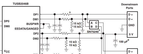
The datasheet shows a matching network with 22 pF shunt caps and 27 ohm series resistors.

Here is a note about D:

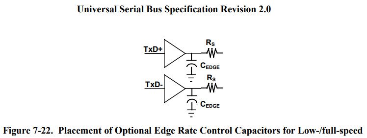
The USB spec agrees with this:

My questions:

  1. Why does the spec have the shunt cap, C[EDGE], on the source side of the series resistor rather than on the line side?  
  2. Are there any recommended ways to change the matching network to reduce EMI?  Is there a register setting that affects drive strength?  
  • Hi Charles,

    The shunt cap is considered part of the 75 pF lumped capacitance allowed at the transceiver.  There is additional capacitance inherent in the board trace and the cable on the other side of the series resistor.

    There is no way to adjust drive strength of the TUSB2046 hub.  The edge rate caps can be adjusted in value as long as they are matched. they can range from 10 pF to 47 pF.  How is the shield ground of the cable connected to the digital ground?  Depending on the setup, we have seen direct  groundconnections work or improvements by adding capacitors and a 1M resistor between chassis ground and shield ground.

    Regards,

    JMMN

  • JMMN said:

    How is the shield ground of the cable connected to the digital ground?  

    The USB connector shied is directly connected to digital ground.  I am checking if the cable they're plugging into is grounded.  

    JMMN said:

    Depending on the setup, we have seen direct  groundconnections work or improvements by adding capacitors and a 1M resistor between chassis ground and shield ground.

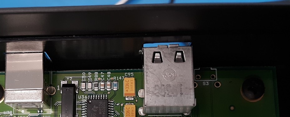
    One of my USB connectors has tabs intended to connect the connector enclosure to the product enclosure.  

    What do you mean by adding capacitors?  I can get connecting two isolated grounds with 1M, so that one is not floating, but where would the caps come into this?  

    Thanks for responding so fast.

  • Hi Charles,

    So there are a lot of different solutions for connecting the two grounds:  

    1. short them

    2. add a 1M resistor and 100 nF cap  in parallel to isolate and decouple the grounds - the cap value can be smaller, or more than one can be used

    3. add a ferrite bead between the grounds

    All of them are valid solutions, but we use the resistor and cap options on our board since it is the easiest to modify if needed.  Here's a different USB hub with the RC circuit between the grounds:  https://www.ti.com/lit/ug/sllu219/sllu219.pdf

    Regards,

    JMMN