This thread has been locked.

If you have a related question, please click the "Ask a related question" button in the top right corner. The newly created question will be automatically linked to this question.

DP83869HM: DP83869HM : How to use MII mode

Part Number: DP83869HM
Other Parts Discussed in Thread: DP83869

Hi team,

We want DP83869HM  to work in MII to copper  mode.But we didn't succeed,and RJ45 is still not linked.

we want to know how to use MII mode? or how should I configure for strap connections resistor for MII to copper ?

Register seting ,as follows

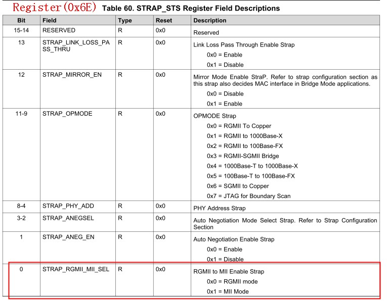
OP_MODE_DECODE (Address = 0x1DF)----->write 0x0060 to 0x1DF( OP_MODE_DECODE  )

BMCR (Address = 0x0) -----------------------------> write 0x2100 to 0x00(BMCR )

GEN_CFG1 Register (Address = 0x9) ----------> write 0x1000 to 0x09( GEN_CFG1).

Regards,

Johnny

  • Hi Johnny, 

    Please ensure you are including a software restart after configuring the device for MII to Copper mode. Write register 0x001F=0x4000 to set the device in the proper mode after the registers are completed.

    Regards,
    Justin 

  • Hi Justin,

    We tried to write register 0x001F = 0x4000, but it didn't succeed. After wirte 0x1F = 0x4000, read register 0x1F ,value :0x1F=0x0000.  And include writing register 0x001F=0x8000 was still unsuccessful.

    We found that we could write 0x0001 to 0x1F.

    Read back from register,as follows

    BMCR(0x00): 2100

    BMSR(0x01): 7949

    PHYIDR1(0x02): 2000

             PHYIDR2(0x03): A0F1

             ANAR(0x04): 0181

            GEN_CFG1(0x09): 1000

            PHY_STATUS(0x11): 6802

            OP_MODE_DECODE(0x01DF): 0060

    Regards,

    Johnny

  • Hi Johnny,

    After writing 0x001F=4000, the register will initiate a software restart and read 0x001F=0x0000 after completed the restart, so that is expected. 

    After completing this, the device will be in MII to Copper mode. If you continue having problems getting link on the MDI it is likely a separate issue from entering MII to Copper mode. 

    Regards,
    Justin 

  • Hi Justin,

    After writing 0x001F=4000,the value of the read register( 0x1F) is 0x00.This is not a problem.But  RJ45 is still not linked.

    another problem is after writing 0x01DF = 0x0060 , Read register 0x6E = 0x20A6.

    we set the  OP_MODE_DECODE ( 0x1DF)  bit ( bit 5)  to  1, to use MII ,but  STRAP_STS Register (Address = 0x6E)  bit ( bit 0)  still  0 .

    how should I configure for  resistor to set  MII to copper  or make  RJ45 to link?

    according to datasheet:

    (1)

    (2)

    Regards,

    Johnny

  • Hi Justin,

    We also want to know how to ensure software restart  success after write 0x001F=4000 ?

    just read 0x001F=0x0000 can ensure software restart  success?

    Regards,

    Johnny

  • Hi Johnny,

    Yes, that is correct.

    Regards,
    Justin 

  • Hi Justin,

    how should I configure for  resistor to set  MII to copper  or make  RJ45 to link  ?

    how should I do next step? 

    This problem has been bothering me for several days.

    I'm waiting for your reply

    Regards,

    Johnny

  • Hi Johnny, 

    Can you please share the schematic you are using for this application and describe what link partner and capabilities you are using to link?

    I would suggest performing an analog or digital loopback test to verify the MII interface between the PHY and the MAC as well.

    Regards,
    Justin 

  • Hi Justin,

    These are our schematic :

    We also try to take a MII loopback test. we will get back to you.

    Regards,

    Johnny

  • Hi Johnny, 

    Please check register 0x6E and verify that the strap settings you are targeting are reflected as enabled in this register. It appears that you have mirror mode enabled (RX_CTRL pulled high), and are forcing 100M MDI mode on LED_0, LED_1, LED_2. Is LED 2 pulled high through R13 and also connected to the RJ45 pull-down resistor R20? Please confirm that LED_2 is being strapped properly.

    Regards,
    justin 

  • Hi  Justin,

    "LED2/nINTSEL"  and “ LED2”  are not the same Net. 

    Register 0X006E = 0X20A6

    Register 0x0009 = 6802

    straps for RGMII/SGMII to Copper

    Regards,

    Johnny

  • Hi  Justin,

    "LED2/nINTSEL"  and “ LED2”  are not the same Net. 

    Register 0X006E = 0X20A6

    Register 0x0009 = 6802

    straps for RGMII/SGMII to Copper

    Regards,

    Johnny

  • Hi Justin,

    " LED2/nINTSET"   and  " LED2"  are different Net.

    Register 0x006E = 0x20A6
    Register 0x0011 = 0x6802

    another Register value:

    BMCR(0x00): 2100
    ANAR(0x04): 0001
    GEN_CFG1(0x09): 1000
    PHY_STATUS(0x11): 6802

    according to SNLA318:

    Configuration for MII-to-Copper is accomplished by setting bit 5 of register CTRL (0x01DF) to 1. 
    We tried to do that( Write 0x0060 to Register 0x1DF ), but  Read back the value of Register (0x006E = 0x20A6).
    What's wrong with what we're doing.
    Regards,
    Johnny
  • Hi Johnny,

    Register 0x006E reflects what values are latching into the bootstrap settings during power on and reset. Updated register 0x01DF will not update register 0x006E. To confirm you are in MII mode, register 0x1DF should be updated. You can also perform analog or digital loopback to confirm the MAC data transfer can be conducted over the MAC interface. 

    Can you please describe the link partner you are using for this test? Is it an identical DP83869 board or something else?

    Regards,
    Justin 

  • Hi Justin,

    1. We already perform MII_Loopback 、Analog_Loopback and digital loopback to validate communications

    between the MAC and the PHY on our board.  Data are not  looped back prior to the Analog_Loopback and digital loopback  mode. 

    MII loopback is ok . We can get data  on TX_D1~TX_D4   RX_D1~RX_D4  .pins

     What shall we do next step ? 

    Regards,

    Johnny


  • Hi Johnny,

    I would like to confirm that all MII, Digital, and Analog loopback modes show data looped back to the MAC? 

    What is the link partner you are using to establish link with the DP83869? Have you confirmed that you are using a MDI (crossed) cable and not a MDIX (straight) cable? 

    Can you also share the register information for 0x0000-0x001F in the state you are trying to establish link?

    Regards,
    Justin 

  • Hi Justin,

    (1) Only MII loopback mode can show data loop back to the MAC, but  Digital, and Analog loopback  can't.

    In MII loopback mode  Test, we can  see that it  is sending  and receiving packages with an oscilloscope. But the other mode does not.

    Do we need to configure any more registers?

    (2) we already changed the straps for Copper interface to  "Auto-negotiation, 1000/100/10 advertised, Auto MDI-X".

    The current  strap configuration as follows:

    RX_D2, RX_D3 & JTAG_TDO (2:0) = 000  (Default).

    LED [2:0] = 000 -  Auto-negotiation,1000/100/10 advertised,Auto MDI-X.

    (3)  We useing the XMOS with DP83869HM on our board. and we would like to set MII-to-Copper mode .

    Our operation:

    Resst chip---> Read  some register --> wait for  phy is powered down -->  write 0x0060 to register 0x01DF--> software restart --> wirte 0x2100 to Register 0x00 --> Read 0x00~0x1F Register--> loopback Seting

    Here is register data:

    phy_address:0x0A BMCR(0x00):                         2100

    phy_address:0x0A BMSR(0x01):                         6149

    phy_address:0x0A PHYIDR1(0x02):                    2000

    phy_address:0x0A PHYIDR2(0x03):                     A0F1

    phy_address:0x0A ANAR(0x04):                          0000

    phy_address:0x0A ALNPAR(0x05):                      0000

    phy_address:0x0A ANER(0x06):                          0000

    phy_address:0x0A ANNPTR(0x07):                      2001

    phy_address:0x0A ANLNPTR(0x08):                    0000

    phy_address:0x0A GEN_CFG1(0x09):                 0300

    phy_address:0x0A GEN_STATUS1(0x0A):           0000

    phy_address:0x0A REGCR(0x0D):                       401F

    phy_address:0x0A ADDAR(0x0E):                       20A0

    phy_address:0x0A 1KSCR(0x0F):                        F000

    phy_address:0x0A PHY_CONTROL(0x10):          5048

    phy_address:0x0A PHY_STATUS(0x11):              0002

    phy_address:0x0A INTERRUPT_MASK(0x12):    0000

    phy_address:0x0A INTERRUPT_STATUS(0x13): 0000

    phy_address:0x0A GEN_CFG2(0x14):                  29C7

    phy_address:0x0A RX_ERR_CNT(0x15):              0000

    phy_address:0x0A BIST_CONTROL(0x16):          0000

    phy_address:0x0A GEN_STATUS2(0x17):            0040

    phy_address:0x0A LEDS_CFG1(0x18):                 6150

    phy_address:0x0A LEDS_CFG2(0x05):                 4444

    phy_address:0x0A LEDS_CFG3(0x1A):                 0002

    phy_address:0x0A ALNPAR(0x1E):                        0012

    phy_address:0x0A ALNPAR(0x1F):                        0000

  • Hi Johnny, 

    You have set the device for auto-negotiation through strap settings and then disabled auto-negotiation through register (0x0000=0x2100 will force the device into 100M speed and not allow auto-negotiation). Are you attempting to establish a link through auto-negotiation, or the link partner already forced into 100M mode as well?

    For digitial and analog loopback, please confirm that you are setting register 0x0016 to the desired mode only. MII loopback in register 0x0000 should not be enabled in other loopback modes. Can you provide your loopback settings?

    Regards,
    Justin 

  • Hi Justin,

    1. We've removed that line of code.( wirte 0x2100 to Register 0x00),and just reserves  strap settings as follows:

    RX_D2, RX_D3 & JTAG_TDO (2:0) = 000  (Default).

    LED [2:0] = 000 -  Auto-negotiation,1000/100/10 advertised,Auto MDI-X.

    2.set MII loopback mode :

    according to snls614A datasheet at 9.3.4.1.1 MII Loopback

    "In 100Base-TX mode after MII loopback is enabled through register 0x00, it is necessary to write 0x0004 to register 0x16 for proper operation of MII Loopback."

    we just set the bit 14 of register 0x00  to 1 ,and  write 0x0004 to register 0x16. The test results were successful.

    Here is register data:

    ---MII loopback mode

    phy_address:0x0A BMCR(0x00): 4140
    phy_address:0x0A BMSR(0x01): 6149
    phy_address:0x0A PHYIDR1(0x02): 2000
    phy_address:0x0A PHYIDR2(0x03): A0F1
    phy_address:0x0A ANAR(0x04): 0000
    phy_address:0x0A ALNPAR(0x05): 0000

    phy_address:0x0A ANER(0x06): 0000
    phy_address:0x0A ANNPTR(0x07): 2001
    phy_address:0x0A ANLNPTR(0x08): 0000
    phy_address:0x0A GEN_CFG1(0x09): 0000
    phy_address:0x0A GEN_STATUS1(0x0A): 4000

    phy_address:0x0A REGCR(0x0D): 401F
    phy_address:0x0A ADDAR(0x0E): 20A0
    phy_address:0x0A 1KSCR(0x0F): F000
    phy_address:0x0A PHY_CONTROL(0x10): 5048
    phy_address:0x0A PHY_STATUS(0x11): 0002

    phy_address:0x0A INTERRUPT_MASK(0x12): 0000
    phy_address:0x0A INTERRUPT_STATUS(0x13): 0000
    phy_address:0x0A GEN_CFG2(0x14): 29C7
    phy_address:0x0A RX_ERR_CNT(0x15): 0000
    phy_address:0x0A BIST_CONTROL(0x16): 0004

    phy_address:0x0A GEN_STATUS2(0x17): 0040
    phy_address:0x0A LEDS_CFG1(0x18): 6150
    phy_address:0x0A LEDS_CFG2(0x05): 4444
    phy_address:0x0A LEDS_CFG3(0x1A): 0002
    phy_address:0x0A ALNPAR(0x1E): 0012
    phy_address:0x0A ALNPAR(0x1F): 0000

    3.set Digitial and Analog loopback mode :  we just write 0x0008 to register 0x16 or write 0x0004 to register 0x16.But the test results were unsuccessful.

    Is this the right way to go ?

    Here is register data:

    ---Digitial loopback mode or  Analog loopback mode 

    phy_address:0x0A BMCR(0x00): 0140
    phy_address:0x0A BMSR(0x01): 6149
    phy_address:0x0A PHYIDR1(0x02): 2000
    phy_address:0x0A PHYIDR2(0x03): A0F1
    phy_address:0x0A ANAR(0x04): 0000
    phy_address:0x0A ALNPAR(0x05): 0000

    phy_address:0x0A ANER(0x06): 0000
    phy_address:0x0A ANNPTR(0x07): 2001
    phy_address:0x0A ANLNPTR(0x08): 0000
    phy_address:0x0A GEN_CFG1(0x09): 0000
    phy_address:0x0A GEN_STATUS1(0x0A): 4000

    phy_address:0x0A REGCR(0x0D): 401F
    phy_address:0x0A ADDAR(0x0E): 20A0
    phy_address:0x0A 1KSCR(0x0F): F000
    phy_address:0x0A PHY_CONTROL(0x10): 5048
    phy_address:0x0A PHY_STATUS(0x11): 0002

    phy_address:0x0A INTERRUPT_MASK(0x12): 0000
    phy_address:0x0A INTERRUPT_STATUS(0x13): 0000
    phy_address:0x0A GEN_CFG2(0x14): 29C7
    phy_address:0x0A RX_ERR_CNT(0x15): 0000
    phy_address:0x0A BIST_CONTROL(0x16): 0004

    phy_address:0x0A GEN_STATUS2(0x17): 0040
    phy_address:0x0A LEDS_CFG1(0x18): 6150
    phy_address:0x0A LEDS_CFG2(0x05): 4444
    phy_address:0x0A LEDS_CFG3(0x1A): 0002
    phy_address:0x0A ALNPAR(0x1E): 0012
    phy_address:0x0A ALNPAR(0x1F): 0000

    Regards,

    Johnny

  • Hi Johnny,

    The configuration for MII and Analog/Digital loopback is correct. In Analog/Digital loopback modes, auto-negotiation is disabled in register 0x0000[12]. Can you confirm the strap settings are correct and provide the register 0x006E data for the loopback mode and normal operation?

    Regards,
    Justin 

  • Hi Justin,

    We ran multiple tests by changing different patterns between "  LED [2:0] = 000 -  Auto-negotiation,1000/100/10 advertised,Auto MDI-X."  and  " LED [2:0] =111 -  Forced 100M, full duplex, MDI-X mode"

    1.  we've run some tests, and we've gotten consistent answers among  MII loopback、Digital loopback and Analog loopback mode. All the values tested were  0x006E = 0x20AE.

    2.on our tests, MII loopback and Digital loopback were already successful,but  Analog loopback was still  unsuccessful .

     Regards,
    Johnny

  • Hi Johnny, 

    In analog loopback mode, can you confirm that there is proper termination on the MDI pins of the PHY? There should be 100ohm differential termination at the RJ45 connector (This can be 100ohm resistor between TD_P and TD_M or another PHY as a link partner present).

    Regards,
    Justin 

  • Hi Justin,

    1.We've run some tests  and  check  details are correct  again.  then we had unintentionally found that cable was loose, so we ran tests  aggin. Finally  analog loopback was successful .Then  we just ran ICMP DEMO  but  we can not ping IP successful . and that Register 0x11= 0x6B02,(the bit 10  is 0 ,link is down ). 

    What's this problem?

    Regards,

    Johnny

  • Hi Johnny,

    I'm glad we've resolved the MII issue and confirmed you are in the correct MAC mode. 

    Please describe the link partner you are using to establish link. Are you using auto-negotiation or forced speed? Please share the register settings 0x0000-0x0011 when you are attempting to establish link.

    Regards,
    Justin 

  • Hi Jutin,

    first ,thanks for your all reply . These  really helped me a lot.

    Then , we used  forced speed mode for ICMP tests.

     we just connected our board to the switch with  cable.and that using another cable  connect  our computer to the switch. But we can not ping IP successful.

    Register value:

    phy_address:0x0A STRAP_STS (0x6E): 20AE
    phy_address:0x0A BMCR(0x00): 2100
    phy_address:0x0A BMSR(0x01): 7949
    phy_address:0x0A PHYIDR1(0x02): 2000
    phy_address:0x0A PHYIDR2(0x03): A0F1
    phy_address:0x0A ANAR(0x04): 0181

    phy_address:0x0A ALNPAR(0x05): 0000
    phy_address:0x0A ANER(0x06): 0064
    phy_address:0x0A ANNPTR(0x07): 2001
    phy_address:0x0A ANLNPTR(0x08): 0000
    phy_address:0x0A GEN_CFG1(0x09): 1000
    phy_address:0x0A GEN_STATUS1(0x0A): 0000

    phy_address:0x0A REGCR(0x0D): 401F
    phy_address:0x0A ADDAR(0x0E): 20AE
    phy_address:0x0A 1KSCR(0x0F): F000
    phy_address:0x0A PHY_CONTROL(0x10): 5028
    phy_address:0x0A PHY_STATUS(0x11): 6B02

    Regards,

    Johnny

  • Hi Johnny,

    Can you verified that your cable and link partner are expected the signals in MDI mode, and not MDIX. In forced modes this is something to verify.

    Two additional tests to try:

    1. Change the DP83869 from slave mode to master mode in register 0x0009[11]. Set this to '1' for Master mode. 
    2. Will your switch and PC support auto-negotiation? Can you test with auto-neg enabled? 

    Regards,

    Justin