This thread has been locked.

If you have a related question, please click the "Ask a related question" button in the top right corner. The newly created question will be automatically linked to this question.

DP83869HM: IEEE802.3 Compliance Testing Scripts for the DP83869

Part Number: DP83869HM
Other Parts Discussed in Thread: DP83869

Hi team,

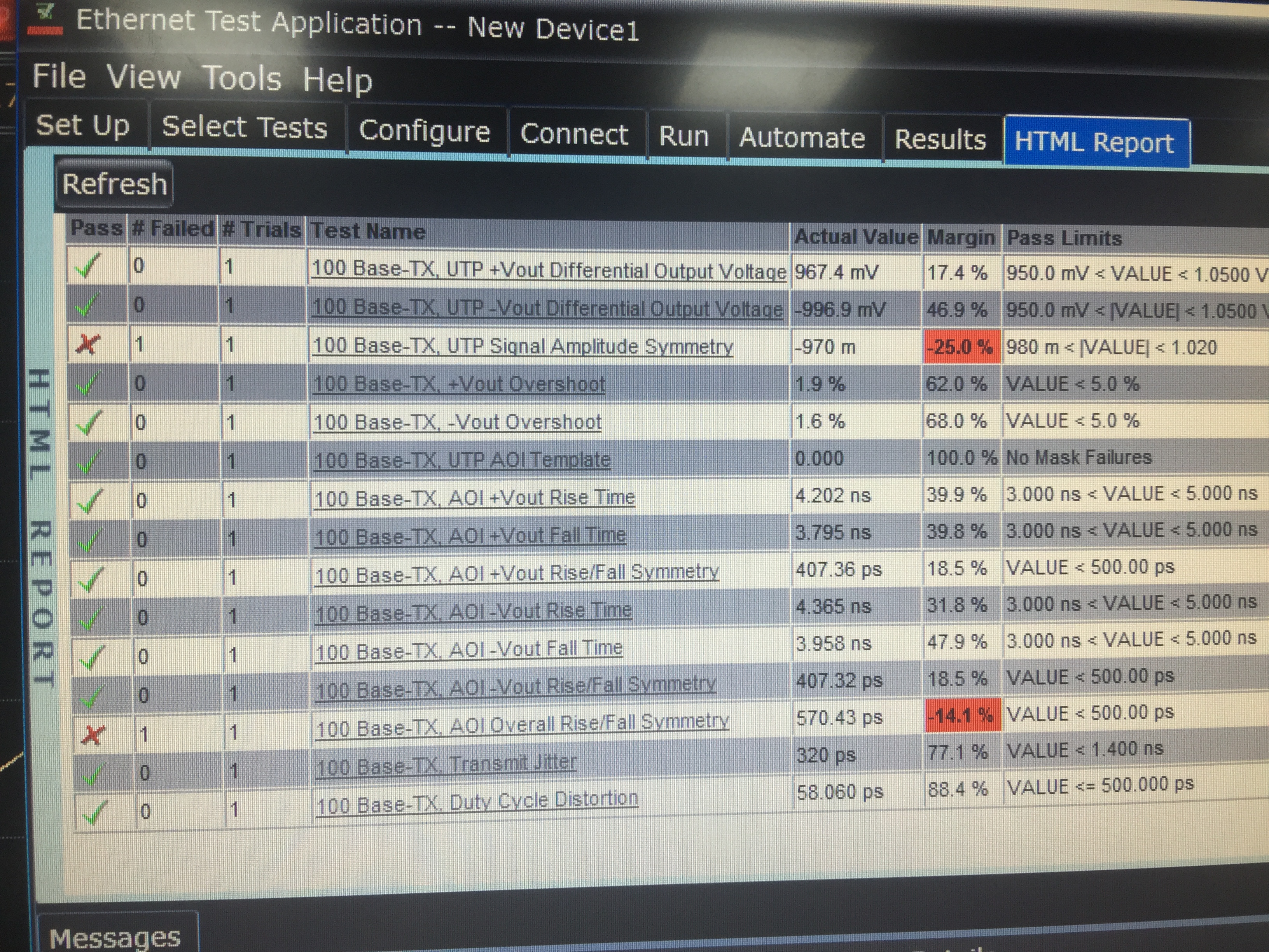
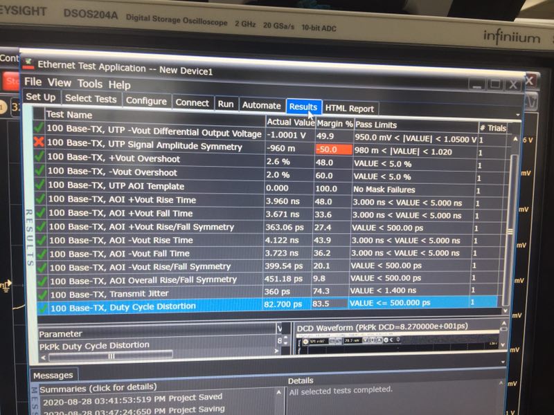
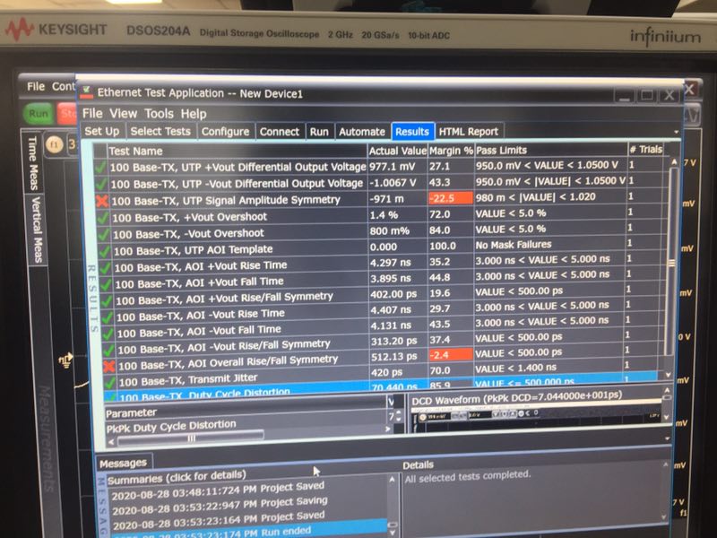
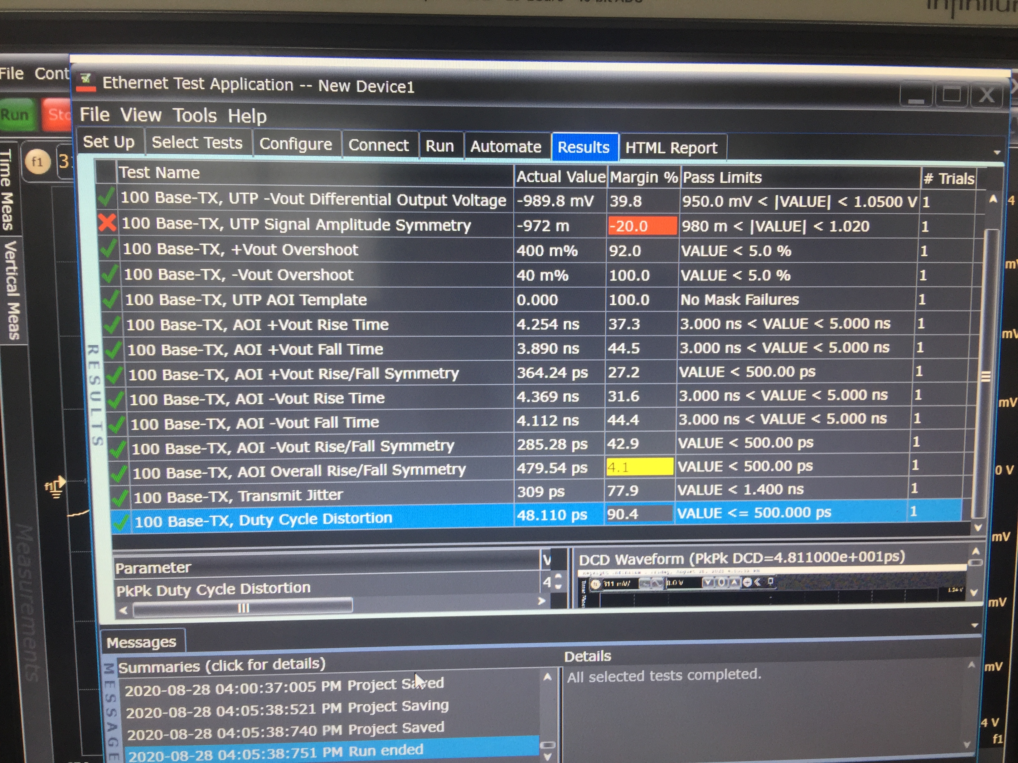
My customer is using DP83869 need pass IEEE802.3 Compliance Test.  Do we have IEEE802.3u Compliance Testing Scripts for the DP83869HM? 

By the way, is the IEEE802.3 Compliance Test require DP83869 be configured as duplex or half duplex mode?

Thank you

Yunjing

  • Hi Yunjing,

    The DP83867 guide for Ethernet compliance test scripts can be used as a guide for the DP83869HM : https://www.ti.com/lit/an/snla239a/snla239a.pdf 

    I've included the DP83869HM scripts below for 1000M Compliance tests below. The IEEE Compliance Tests don't require full duplex of half duplex mode to be set as these are measuring the PMA output of the PHY.

    Test Mode 1

    001F<-8000

    0000<-0140

    0010<-5008

    0025<-0480 (All channels)

    0009<-3B00

    01D5<-F508

    00A6<-0683


    Master Operation (linkup)

    001F <- 8000

    0000 <- 1140

    0010 <- 5008

    0009 <- 1B00

    0170 <- 0810 (Channel A)

    0170 <- 0910 (Channel B)

    0170 <- 0A10 (Channel C)

    0170 <- 0B10 (Channel D)


    Slave Operation (linkup)

    001F <- 8000

    0000 <- 1140

    0010 <- 5008

    0009 <- 1300

    0170 <- 0810 (Channel A)

    0170 <- 0910 (Channel B)

    0170<- 0A10 (Channel C)

    0170 <- 0B10 (Channel D)


    Test Mode 2

    001F <- 8000

    0000 <- 0140

    0010 <- 5008

    0025 <- 0400 (Channel A)

    0025 <- 0420 (Channel B)

    0025 <- 0440 (Channel C)

    0025 <- 0460 (Channel D)

    0009 <- 4B00

    0170 <- 0810 (Channel A)

    0170 <- 0910 (Channel B)

    0170 <- 0A10 (Channel C)

    0170 <- 0B10 (Channel D)

    00C6 <- 0010


    Test Mode 3

    001F <- 8000

    0000 <- 0140

    0010 <- 5008

    0025 <- 0400 (Channel A)

    0025 <- 0420 (Channel B)

    0025 <- 0440 (Channel C)

    0025 <- 0460 (Channel D)

    0009 <- 6B00

    "0170 <- 0810 (Channel A)

    0170 <- 0910 (Channel B)

    0170 <- 0A10 (Channel C)

    0170 <- 0B10 (Channel D)"

    00C6 <- 0010


    Test Mode 4

    001F<-8000

    0000<-0140

    0010<-5008

    0025<-0400 (Channel A)

    0025<-0420 (Channel B)

    0025<-0440 (Channel C)

    0025<-0460 (Channel D)

    0009<-8B00

    Regards,

    Justin 

  • Hi Justin,

    Thanks you so much! They get right idle waveform with the DEMO scripts.

    However, they failed on Signal Amplitude Symmetry and rise/fall time during 100 Base-Tx compliance test, as below test result shows.

    Do you know if any wrong register value can cause this issue?

    And one more question, is test mode 5 necessary for 100Base-Tx compliance test? If IEEE didn't specified test mode for 100Base-Tx compliance test (Let me know if my information is wrong), why we suggest use Scrambled MLT3 Idles for compliance test? Or it is OK to use normal mode for 100Base-Tx compliance test?

    Thanks and best regards

    Yunjing

  • Hi Yunjing,

    Which channel are you seeing the amplitude symmetry and rise/fall time failures on? 

    Yes, test mode 5 is necessary for testing IEEE compliance in 100Base-TX mode. You should not use a normal operation mode because without a link partner, the PHY will send auto-negotiation pulse on the MDI rather than the MLT3 signal.

    Regards,
    Justin 

  • Hi Justin,

    Channel ABCD all fail on amplitude symmetry and rise/fall time.  See below test results.

    My opinion is that amplitude symmetry failure is caused by potential Impedance mismatch, but I don't have clear direction on rise/fall time failure.

    What do you think? Can you pls share your experience on debug the root reasons of this two issues?

    Channel A

    Channel C

    Channel B/D

    Thank you & Best regards

    Yunjing

  • Hi Yunjing,

    Can you provide the magnetic component part number and schematic of the DP83869 MDI pins to connector for this application?

    Regards,
    Justin 

  • Hi Justin,

    Customer found some error in their driver code, so they need to debug the driver code first, then perform the compliance test.

    I will continue discuss with you through email about this issue when they finish software debug.

    And can you pls share a DEMO register configuration configuration for MII to 100Base-Fx(MII to Fiber)? 

    As snla318.pdf said, they write 0x62 into register 0x01DF, LINK up can be recognized normally when the optical fiber cable is inserted, but when the optical fiber cable is pulled out, the device cannot recognize the link down status, and even if the optical fiber cable is inserted again, DP83869 also can not recognize Link Up.

    Thank you

    Yunjing

  • Hi Justin,

    I would like to keep this thread for IEEE compliance discussion, so I set up a new thread for Fiber mode link issue. Thank you!

    Yunjing

  • Hi Yunjing,

    I understand, please share the compliance test results when the driver software is resolved.

    Regards,
    Justin 

  • Hi Yunjing,

    I will close this thread while the customer resolves their driver and waits for updated compliance testing results. Please open another thread and reference this post if you need further discussion. 

    Regards,
    Justin