This thread has been locked.

If you have a related question, please click the "Ask a related question" button in the top right corner. The newly created question will be automatically linked to this question.

TUSB320: BULK CAPcircuit in RDP mode

Part Number: TUSB320

Dear sir:

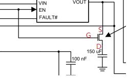
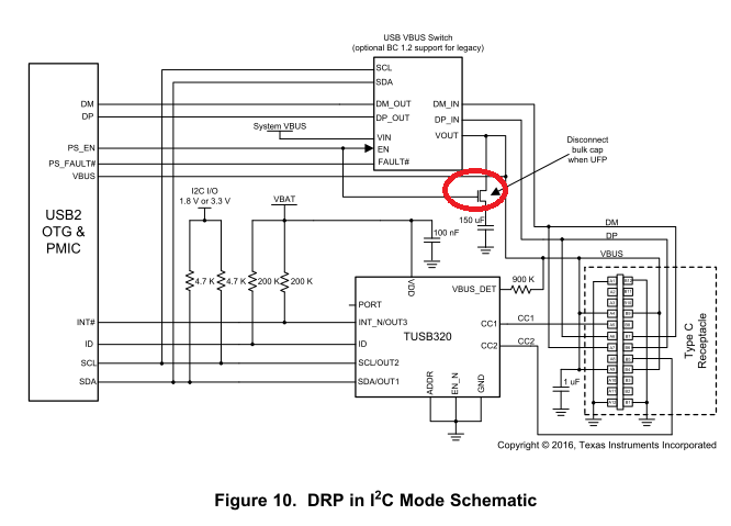
We're confusion about the BULK CAPcircuit in the datasheet reference design of TUSB320, what's kind MOS used here, NMOS or PMOS?

For NMOS, when EN pull high, Vbus will charge the bulk cap, but when the CAP fully charged, the voltage on MOS_S will be high, Vgs<Von, the Vds stops and then discharge...Vgs>Von, Vds open...finally, the voltage on CAP keeps ~2.1V ; For PMOS, EN and Vbus pull high, Vds stops

In our application, we put a NMOS here, the voltage on VBUS keeps ~2.1V and detect Devices fail on most boards, it's really bad for us in this stage.

I think the MOS and the bulk cap should change the position here, please help to check about this issue, thanks

Sercomm RD Sally Feng

  • Hi Sally,

    In the image this would be a PMOS (only expecting 5V on VBUS), in UFP mode the cap should be disconnected but Vbus should still be high as its provided by connected DFP port. Could you describe your testing sequence?

  • Dear sir:

    If it's a PMOS, in UFP mode, EN=0V, VBUS=5V, Vgs=-5V, the MOS would be open, is that a problem?

    in our application, we put a NMOS here, when we insert a device on USBC port, EN=3.3V, the MOS open at the beginning,  when the CAP fully charged, the voltage on MOS_S will be high, Vgs<Von, the Vds stops and then discharge...Vgs>Von, Vds open...finally, the voltage on CAP keeps ~2.1V ; the device couldn't be powered and detected failed.

    if we exchange the position of the CAP and the NMOS, it'll be OK for detection and control, as bellow:

  • Hi,

    No, this is intended as the bulk capacitance should be disconnected (switch open) when in UFP mode. If want to use a NMOS device then the connection shown above will achieve the same effect. You should ensure the USBC-PWR_EN has the correct polarity (active low) so that in UFP the bulk capacitance is disconnected from GND. 

  • Dear sir:

    My confusion is that in UFP mode, EN should be low, VBUS=5V, then Vgs=-5V, the PMOS is on, capacitance is connected, that's not excepted ? thanks

  • Hi,

    Your explanation is correct however this depends on EN polarity and will change what kind of device is needed here.