This thread has been locked.

If you have a related question, please click the "Ask a related question" button in the top right corner. The newly created question will be automatically linked to this question.

TPS65988EVM: The TPS65988 PD controller does not PON while the phone insertion in J1 conn- PD Port1

Part Number: TPS65988EVM

Hi,

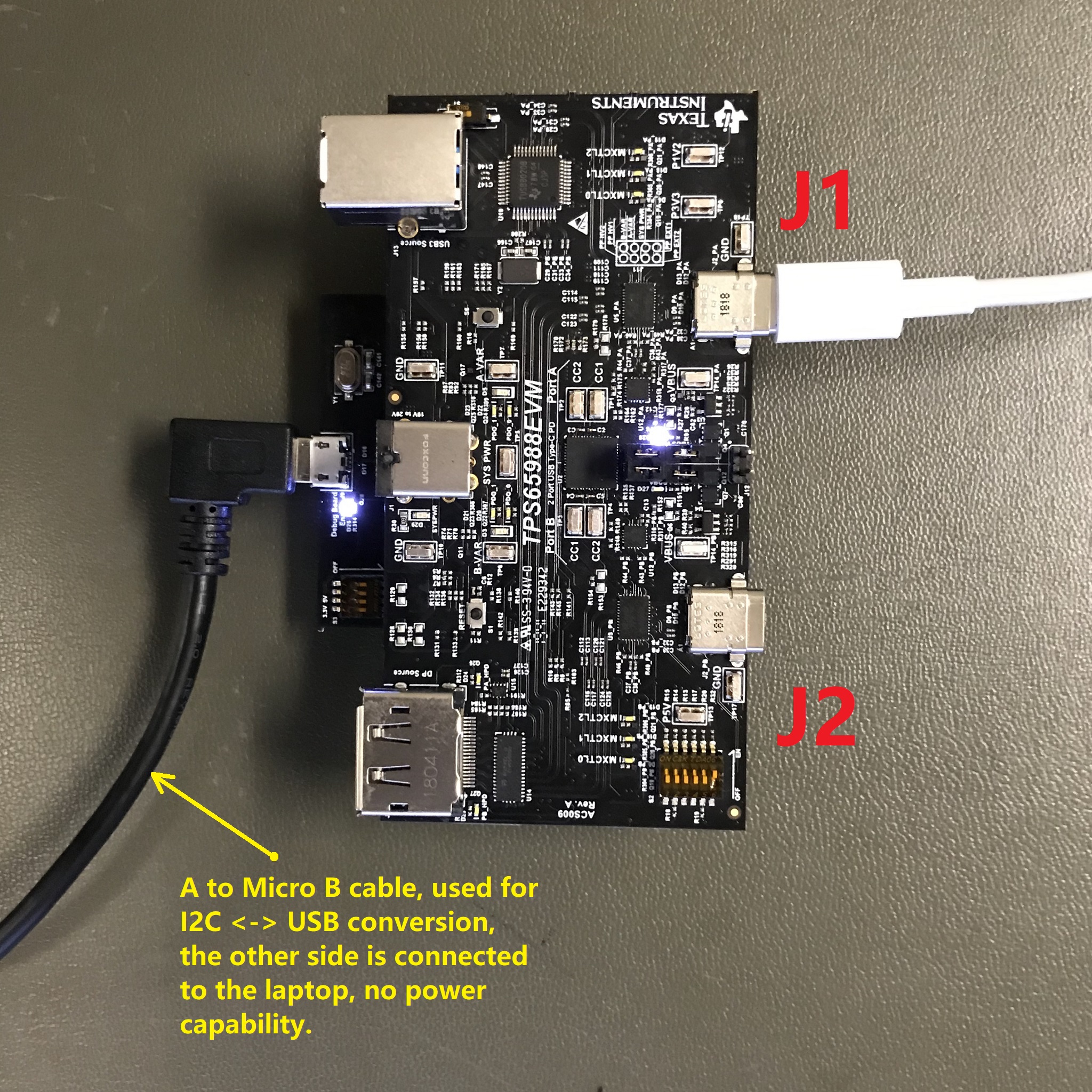
We've built our own bus-powered HUB PCB based on TPS65988EVM PCB.

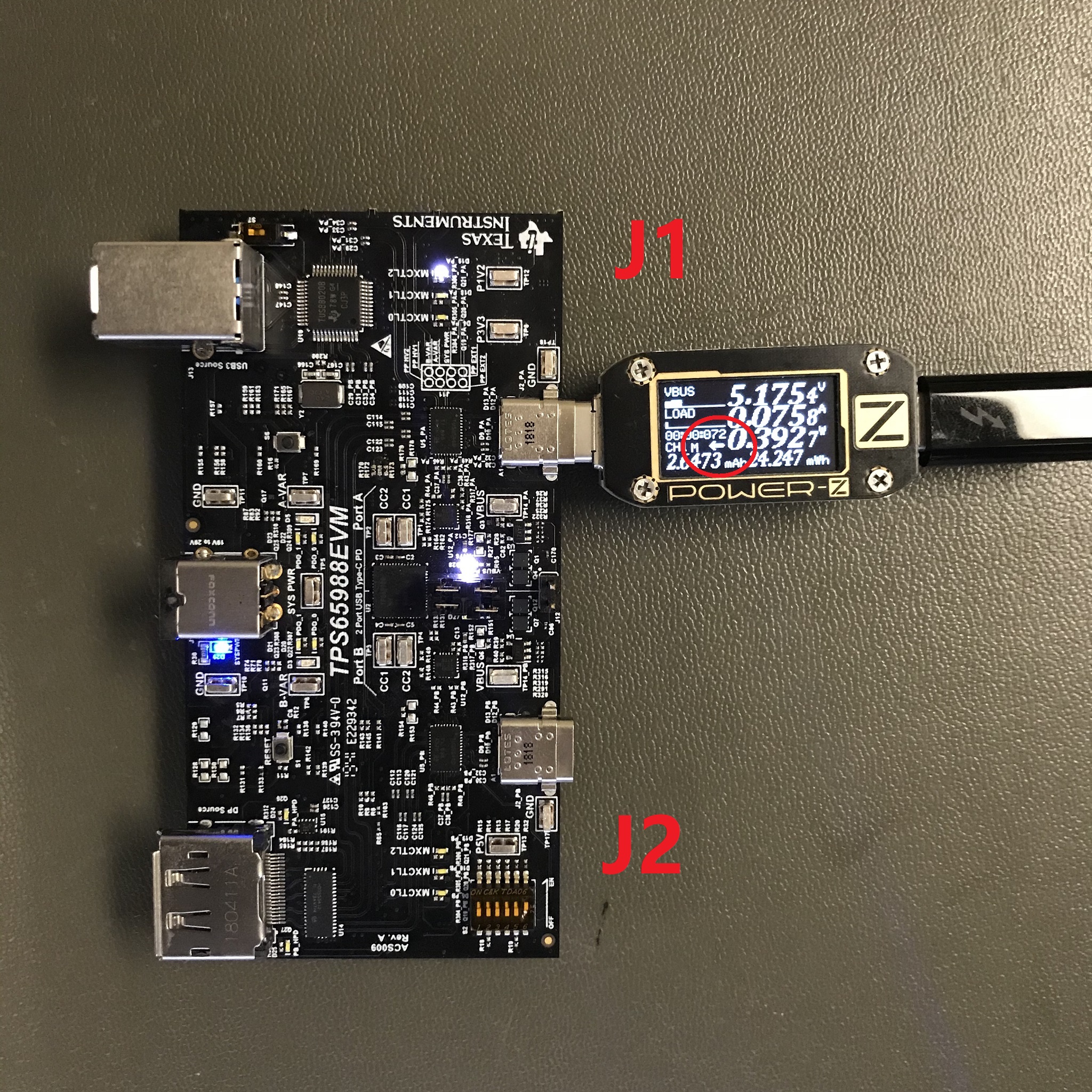
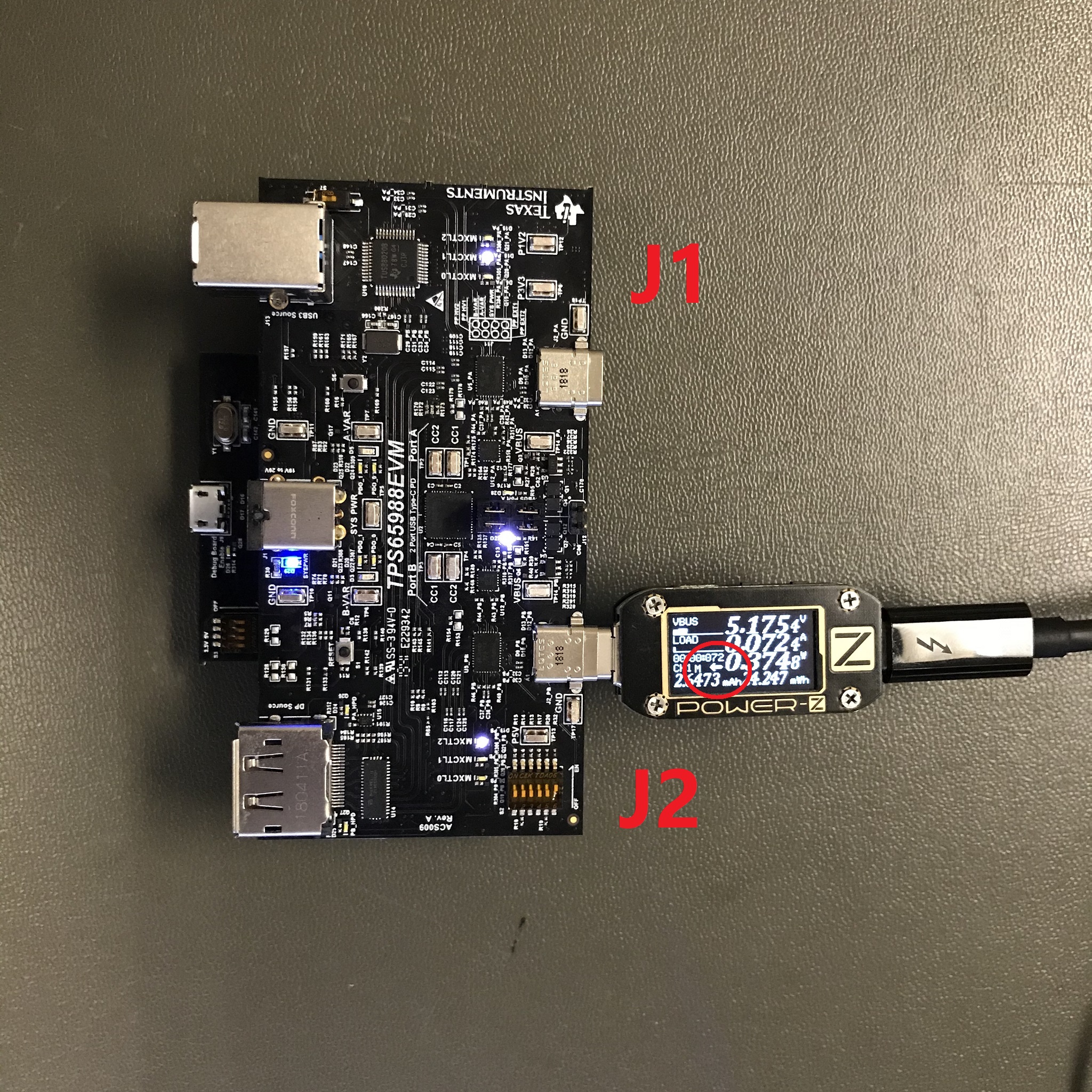
The phone is inserted into J1 male Type C connector.
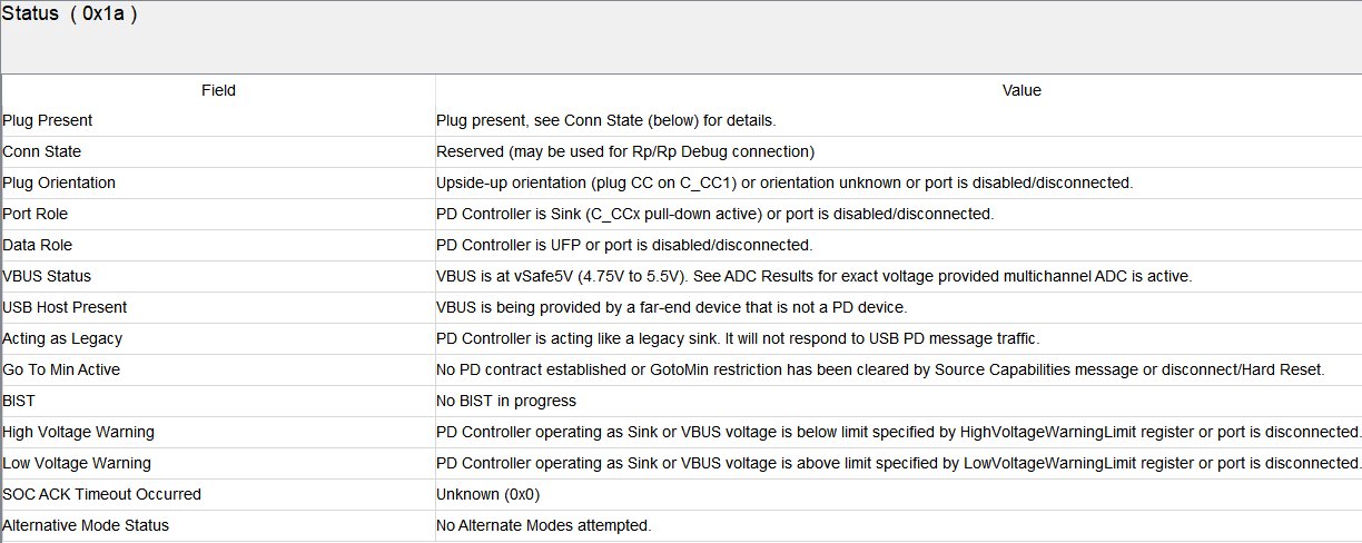
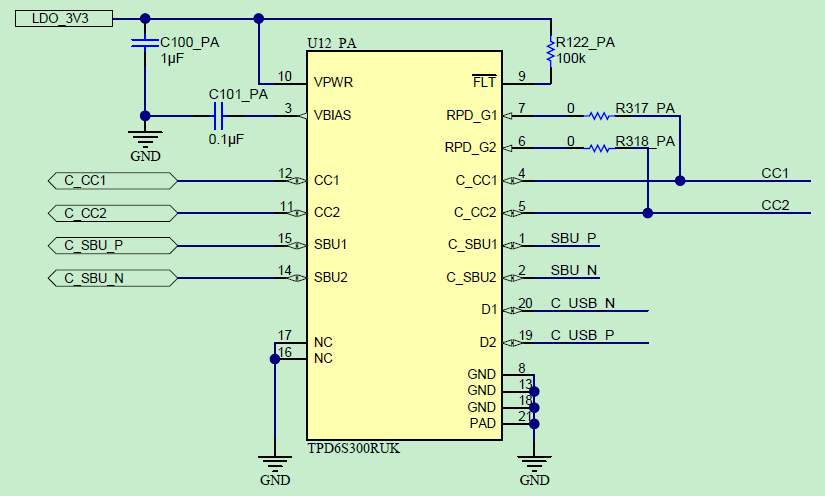
The TPS6S300 IC in “dead/no battery” mode has to put Rd=5.1k pull-down resistors on CC 1&2 signals that will sense to the phone switch into the source mode and enable the VBUS voltage to the HUB. As a result, the phone VBUS does not enable from the phone to the HUB (Source mode).
Please see the attached slides and schematic for the detailed explanation.
Thanks
Vitaliy

  • Hello,

    I've assigned this to the relevant expert who will get back to you soon

  • Hi Adam,

    Could you/expert, please respond?

    Thanks

    Vitaliy

  • Hi Vitaliy,

    Sorry to reply late.

    One question,

    Did you use the default configuration in Application Customization Tool for this application scenario?

    Thanks.

    Bing

  • Hi Bing,

    What do you mean by default configuration?

    I am using the Advanced template type for TPS65988 DRP, prefers power source, or prefers power source and tethered cable.

    I don't have the real tethered cable, but the phone in J1 can be inserted only in one direction. The reversibility is protected mechanically. Does it make sense to use DRP, prefers power source and tethered cable or DRP, prefers power source?

    The pjt and bin files of my project are enclosed.

    Thanks

    Vitaliy

    POC PD Serial Flash ADV_CONF.zip

  • Hi Vitaliy,

    I will try the pjt & bin files you uploaded, and will give you a feedback.

    Thanks.

    Bing

  • Hi Bing,

    Could you please advise and provide your feedback.

    Thanks

    Vitaliy

  • Hi Vitaliy,

    According to the pjt file, I tried it on TPS65988 EVM board and it works, below is the details:

    Try to reproduce  the Experiment 1a:

    1. Use a DRP board (prefers DFP) to emulate a phone,;

    2. Download the pjt into the 988 device, and then EVM Port A corresponds to J1 port and EVM Port B corresponds to J2 port, and use a C-to-C cable to plug in Port A, then the other side of the cable can be regarded as J1;

    3. Cut off the power of 988 EVM to emulate dead battery mode;

    4. Use the DRP board to plug in J1;

    Below is the result:

    As the POWER-Z USB Meter shows, the DRP board (phone) can power J1 port.

    Try to reproduce the Experiment 1b:

    1. Firstly use an A to C cable to plug in a Laptop A receptacle;

    2. Then plug C-side into J1;

    Below is the result:

    The LED on board present, and the device can enter debug mode. From the row of "Acting as Legacy", it can be seen that the port can't support PD, it can just used as a legacy sink cause no CC line in A-to-C cable.

    Try to reproduce the Experiment 2:

    1. Connect DRP board to J2 through a C-to-C cable;

    below is the result:

    J2 port can be powered by DRP port.

    From the above results, it seems that J1 can be power by DRP board, i.e., by phone. And I check the connection of TPD6S300 based on TPS65988 EVM User Guide, below is the circuit of TPD6S300:

    Pin RPD_G1 & RPD_G2 are connected to their relevant CC line pins. 

    Additionally, the waveform of CC lines on J1 connector is as below:

    The behavior of CC1 & CC2 is normal according to the result.

    According to above results, I suggest that check the hardware circuit. If CC2 follows CC1, is it possible that short issue occurs on your board? 

    In the Experiment 3, when open the trace from C_CC2 to RPD_G2, then every phone connection is enabled, have you tried both orientation of the connection?

    Thanks.

    Bing

  • Hi Bing,

    Thanks. I have found the issue with CC2 was also routed into J1 PLUG connector between J1 and PD. 

    The phone is attached directly to J1 without any cable.

    The HUB is PON now when I cut the CC2 line and stayed with only CC1 line.

  • Hi Vitaliy

    It is nice to find out the cause. And if the problem has been solved please close the question.

    Thanks.

    Bing