This thread has been locked.

If you have a related question, please click the "Ask a related question" button in the top right corner. The newly created question will be automatically linked to this question.

TCAN4550-Q1: TCAN4550-Q1 CAN bus transmit issue and SCH Check

Part Number: TCAN4550-Q1
Other Parts Discussed in Thread: TCAN4550, TCAN4550EVM

Hi,

We are using TCAN4550-Q1 for CAN bus for communication. 

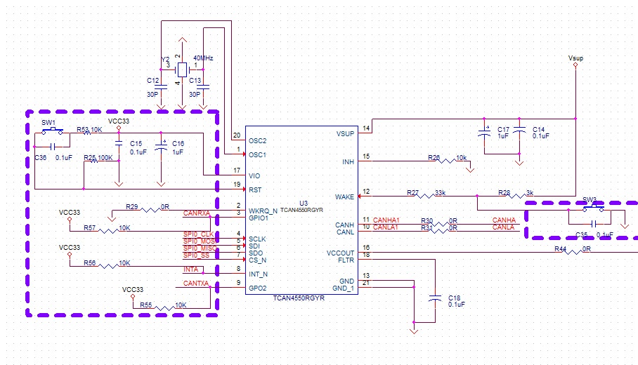
Please help to check whether the schematic is OK?

We use the schematic to product a prototype for test. The SPI communication is work fine, but when I send CAN message to TCAN4550 there is no message goes out from CANH and CANL.

Then I check the TCAN4550 mode. I set it to normal mode sometimes it will success, sometimes it still in standby mode.

When it success to normal mode, I send some CAN message from other device TCAN4550 get the first one or two message then change the mode to standby mode itself.

I test the same way on TCAN4550EVM It work fine, the mode can still keep in normal mode.

Do you have any idea?


  • Ted,

    Thanks for bringing this question to E2E and for all the information about your test setup.

    Two issues I notice immediately with your setup: FLTR pin needs at a minimum 300nF output capacitance, there is only 100nF in your schematic, and VCCOUT needs 10uF of output capacitance, there is none in your setup. One other issue is the CANH and CANL components, are there termination resistors and other filter components elsewhere on the CAN bus? Bus termination is absolutely necessary for CAN communication to propagate correctly.

    It sounds like your device is resetting when you're transmitting CAN frames since it ends up back in standby mode, and not having the right amount of output capacitance on both the FLTR and VCCOUT pins could cause this. The FLTR pin is the filter for the internal regulator that biases the CAN bus. If the CAN bus drivers drive a dominant. without the correct amount of output capacitance, this could place the internal regulator out of regulation and force a device reset through an under voltage condition. 

    When the device ends up in standby mode, do the registers have to be reconfigured as well?

    Regards,

  • Hi Eric,

    After I move the 10uF of output capacitance close to the TCAN4550, the mode is worked fine in normal mode. Transmitting CAN frames is worked fine. But when receiving CAN frames, if frames quickly received the interrupt occurred first one or two then stop occurred. I need to change mode to standby then change back to normal mode. The interrupt can occur again but receive frames quickly it stop again.

    Thanks for the support.

    Regards,

  • Ted,

    When you say "receive frames quickly" does that mean the data rate of the CAN bus increases, or more messages are being sent in succession? And when you say interrupt, is the nINT pin being asserted or do you just mean the CAN communication is interrupted by stopping?

    Can you also read registers 0x0820 and 0x0824 when the CAN communication stops working?

    Regards,

  • Hi Eric,

    It means more messages are being sent in succession. The nINT pin being asserted after receive frames quickly, but I can send frame as normal.
    When nINT pin stop working, The register 0x0820 is 0x000004A2 and register 0x824 is 0x00010001.

    Regards,

  • Kevin,

    The interrupts getting thrown in 0x0820 are CAN silent, global error, CAN error and MCAN_INT. CAN silent, global error, and CAN error are all the result of no communication happening on the bus for longer than one second. And in register 0x824, the interrupts are timestamp wrap around and RX FIFO 0 new message. So the messages are getting received correctly, are you reading them out quick enough before the next message is read? Or are you trying to read out multiple messages at once? And how is your RX FIFO 0 configured?

    Regards,

  • Hi Eric,

    I configured the TCAN4x5x_MRAM_Config as follow, same as the sample code from library.

    TCAN4x5x_MRAM_Config MRAMConfiguration = {0};
    MRAMConfiguration.SIDNumElements = 0;
    MRAMConfiguration.XIDNumElements = 0;
    MRAMConfiguration.Rx0NumElements = 32;
    MRAMConfiguration.Rx0ElementSize = MRAM_64_Byte_Data;
    MRAMConfiguration.Rx1NumElements = 0;
    MRAMConfiguration.Rx1ElementSize = MRAM_64_Byte_Data;
    MRAMConfiguration.RxBufNumElements = 0;
    MRAMConfiguration.RxBufElementSize = MRAM_64_Byte_Data;
    MRAMConfiguration.TxEventFIFONumElements = 0;
    MRAMConfiguration.TxBufferNumElements = 32;
    MRAMConfiguration.TxBufferElementSize = MRAM_64_Byte_Data;

    I try to send messages per 10ms and read the messages quickly as possible. Sometimes it stop again, I need to read out the message manually.
    How can I read out multiple messages at once to resolve there are messages still in RX FIFO 0?

    Regards,

  • Ted,

    With this configuration, you have all received messages going to RX FIFO 0, which is okay for this testing. And there are enough configured FIFO 0 elements with 64 byte data size that you aren't running out of memory to store the received messages.

    When the interrupt pin "stops working" does that mean it goes back to a high level and doesn't go low anymore? Or does it stay low and not go back high? And are you using the interrupt to know when to read the messages from the FIFO space, or are you just reading the FIFO 0 every time a message is sent?

    If you haven't already, I'd recommend looking through the TCAN4550-Q1 Software user's guide to go along with the starter code. 

    Regards,