This thread has been locked.

If you have a related question, please click the "Ask a related question" button in the top right corner. The newly created question will be automatically linked to this question.

TUSB212: Question for TUSB212 failure mode when junction temperature exceeds recommended range

Part Number: TUSB212

Hi Team,

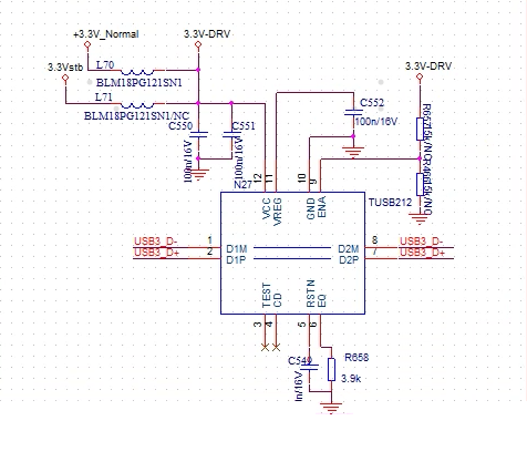
Our customer is using our TUSB212 in their product, and they want to know what's the failure mode for this device when junction temperature exceeds our recommended maximum range(+85C)? Does it will pull low or pull high D+/D- traces or high impedance status? Does it will have any influences for the D+/D- signals or just no function?

Thanks a lot!

  • junction temperature  could exceed recommended maximum range. temperature. there is relationship between junction temp and  ambient temp. Pls check document SPRA953C at ti.com

  • Hi Brian,

    We know that we can exceed the maximum junction temperature, but our question is when we exceeded the maximum junction temperature, we found that our device will stop work, but we do not know the detailed failure mode under this situation. What's the resistance status for D+/D- pins for this over temperature condition?

  • Hi Jacky,

    What is the specific junction temp you are seeing issues at? From my understanding there is no catastrophic failure mode but operating at this temperature is not recommended. If high temperature ratings are needed please use TUSB212-Q1.

  • Hi Malik,

    In customer's application, they used the commercial grade TUSB212, and measured the IC top case temp is around 65C, the USB eye diagram becomes worse and caused USB communication error. So we are suspecting that it should trigger our IC junction temp which cause IC no function, as from datasheet's statement, commercial grade recommended junction temp range is only 0~85C.

    So that's why we want to check the failure mode if we trigger the IC junction temp for TUSB212. Also, can you help to check what's the safety top case temp for our device if customer used commercial grade?

    Thanks.

  • you need TUSB212Q1 device

  • Hi Brian,

    We are trying to test the industrial version firstly, but I'm just curious about it why we design so low junction temp for commercial version? As far as we know most of other commercial ICs will have more than 105C junction temp in TI. Any potential consideration for this specification?

    Thanks.

  • industril version need more liability test,  and took more time. that's why we release commercial version first.

  • Hi Brian,

    We tested the industrial version for TUSB212I in customer's aging test(room temp is around 45C, and humidity is around 60%, IC case temp is around 77C), but it still fails when testing the eye diagram. We checked in normal room temp around 25C the TUSB212I works fine with good eye diagram. When it fails in high room temp, we also checked the IC VREG 1.8V voltage is normal. 

    As the rough calculation for the thermal resistance and junction temp, it should have enough margin for junction temp under this condition(Tj=77C+62C/W*0.1W=83.2C, <<105C), but we do not know why TUSB212I still fails, can you help to give us any clues? Below is customer's schematic for our device. 

    This issue is a little bit urgent for customer's project, kindly help to check it ASAP, thanks a lot!

  • Hi Jacky,

    Could you share the measured eye diagrams and layout for the board the customer is using to test? What is the fail parameter in the test. Please ensure that power is stable during the high temp testing. Does the customer see temp variation from the USB PHY that TUSB212 is redriving? Could you share the customers test setup?

  • Jacky:

        Any update?

  • Issue was resolved in internal thread. 

  • Hi Brian,

    Issue has been closed offline through emails with your team, thanks for the support.

    Update and summary:

    1. Initially the commercial version TUSB212 eye diagram failure rate will be around 0.6% during customer’s aging test(measured IC top case temp about 77°C~80°C), after changing to industrial version TUSB212I, so far no failures reported.
    2. The root cause for TUSB212I Compliance Test Mode eye diagram sometimes failures even under normal room temp, is that we found there is some AC220V voltage leakage for their Oscilloscope, as the earthed pin was not properly connected. After fixing this, by following the steps Malik recommended, no eye diagram failure happened any more.
    3. The root cause for TUSB212I High Speed Mode eye diagram sporadic failures is due to their SoC and USB2.0 Camera enumeration, as from their system log info, we found the camera has been enumerated into full speed device with errors. Customer is still investigating for this software driver problem, but it should be no relation to our device function now.