This thread has been locked.

If you have a related question, please click the "Ask a related question" button in the top right corner. The newly created question will be automatically linked to this question.

DS90UB960-Q1EVM: Activate FrameSync for 2x 953 Serializers

Part Number: DS90UB960-Q1EVM

Hi,

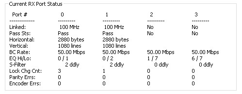
In my setup I have the UB960 EVM, with 2x OV2775 camera sensor modules connected to (via 953 serializers).

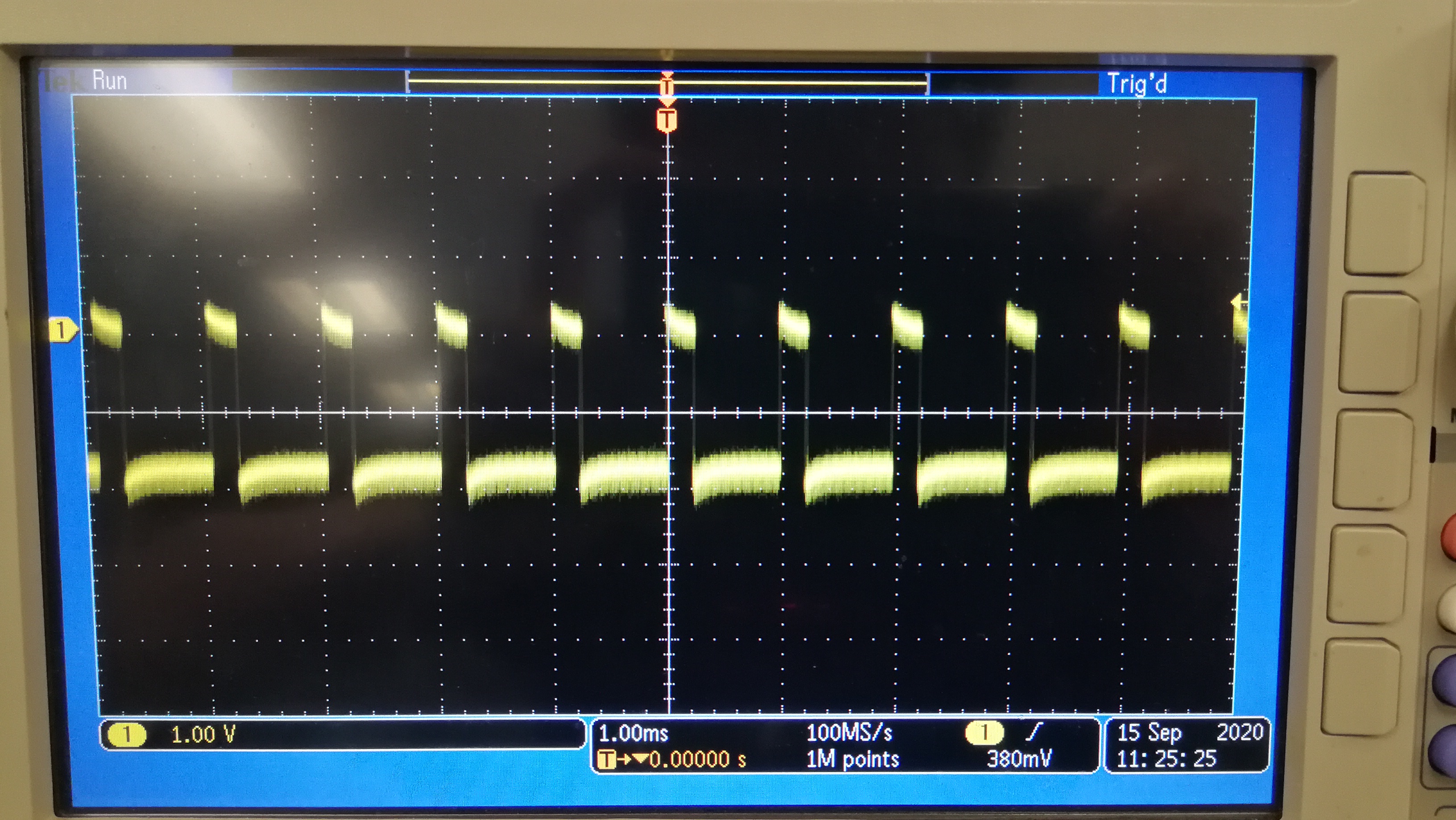
I can't make the FrameSync, generated on GPIO1, propagate from the serializer to the sensors.

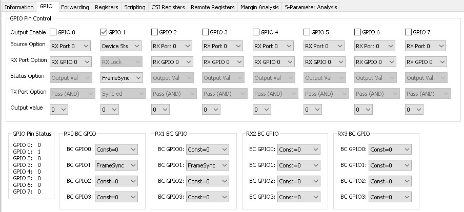
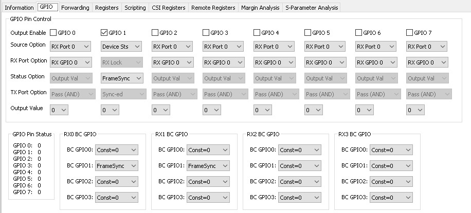
I know that my GPIO is toggling, by looking in the GPIO tab:


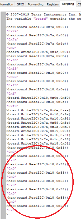
But in the sensor side, the register 0x53 is always ZERO.

My FrameSync configurations are:

def INT_FRAME_SYNC():
	board.WriteI2C(UB960, 0x4C, 0x01) # select port rx0
	board.WriteI2C(UB960, 0x6E, 0xA8) # BC_GPIO_CTL0: FrameSync signal to GPIO1 (GPIO0 = LOW)
	board.WriteI2C(UB960, 0x4C, 0x12) # select port rx1
	board.WriteI2C(UB960, 0x6E, 0xA8) # BC_GPIO_CTL0: FrameSync signal to GPIO1 (GPIO0 = LOW)
	board.WriteI2C(UB960, 0x11, 0x91) # GPIO1_PIN_CTL Register - FrameSync signal; Device Status; Enabled
	board.WriteI2C(UB960, 0x58, 0x5D) # BC FREQ SELECT
	board.WriteI2C(UB960, 0x19, 0x00) # FS_HIGH_TIME_1
	board.WriteI2C(UB960, 0x1A, 0x8A) # FS_HIGH_TIME_0
	board.WriteI2C(UB960, 0x1B, 0x04) # FS_LOW_TIME_1
	board.WriteI2C(UB960, 0x1C, 0xE1) # FS_LOW_TIME_0
	board.WriteI2C(UB960, 0x0F, 0x00)
	board.WriteI2C(UB960, 0x18, 0x03) # Enable FrameSync

And my serializers configurations is:

def SER_CFG(idx):
	board.WriteI2C(idx, 0x1, 0x2) # RESET_CTL - reset all including register
	time.sleep(1)
	board.WriteI2C(idx, 0x02, 0x52) # General_CFG - continous clock, 2-lanes, enable tx crc generator
	time.sleep(0.5)
	board.WriteI2C(idx, 0x06, 0x41) # CLKOUT_CTRL0
	board.WriteI2C(idx, 0x07, 0x28) # CLKOUT_CTRL1 - default
	board.WriteI2C(idx, 0x0E, 0xD0) # GPIO_INPUT_CTRL - gpio[3:0] output enabled, input disabled
	board.WriteI2C(idx, 0x0D, 0x20) # LOCAL_GPIO_DATA - disable remote deserializer gpio data on local gpio
	time.sleep(1)
	board.WriteI2C(idx, 0x0D, 0x2C) # LOCAL_GPIO_DATA - disable remote deserializer gpio data on local gpio + enable remote GPIO1
	time.sleep(1)

idx is the SLAVE_ALIAS for the serializer

Thanks for the support,

Matan

  • Hello,

    the first two screenshots are missing. Can you please re-post them?

  • Hi Hamzeh,

    The GPIO1 toggles in the UB960:

    Link information:

    Thanks,

    Matan

  • Hello Matan,

    In your 960 code I have found two errors:


    1) Register 0x58 needs to be 0x5E not 0x5D. 25Mbps BC is not supported.
    2) Register 0x18 needs to be 0x01 not 0x03. If you write 0x03 that means your FSync signal Hi/Low is 50/50 and this will override your initial High/Low settings.

    Also on the 953 you need to write:

    0x0D[5]=1

    0x0E[5]=1

    0x0E[1]=0

  • Hi Hamzeh,

    It still doesn't work.

    Deserializer configuration:

    def DESER_CFG(ser_alias, sensor_id, sensor_alias):
    	if ser_alias == UB953_1_ALIAS:
    		board.WriteI2C(UB960, 0x4C, 0x01) # FPD3_PORT_SEL - write/read enable for rx0 registers
    	elif ser_alias == UB953_2_ALIAS:
    		board.WriteI2C(UB960, 0x4C, 0x12) # FPD3_PORT_SEL - write/read enable for rx1 registers
    
    	board.WriteI2C(UB960, 0x58, 0x5E) # BCC_CONFIG - always enable i2c pass-through to serializer if decode matches, back-channel is always enabled, back-channel crc generator enabled, back-channel frequency select
    	board.WriteI2C(UB960, 0x5C, ser_alias) # SER_ALIAD_ID
    	time.sleep(0.5)
    	board.WriteI2C(UB960, 0x5D, sensor_id << 1) # SlaveID[0] - slave device id (physical i2c address of the slave device attached to the serializer)
    	time.sleep(0.5)
    	board.WriteI2C(UB960, 0x65, sensor_alias) # SlaveAliad[0] - slave alias id (configures the decoder for detecting transactions designated for an i2c slave device attached to the remote serializer)
    	time.sleep(0.5)
    	board.WriteI2C(UB960, 0x6D, 0x7C) # PORT_CONFIG - select csi-2 mode
    	board.WriteI2C(UB960, 0xD5, 0xF0) # AEQ_MIN_MAX
    	board.WriteI2C(UB960, 0x7C, 0x01) # PORT_CONFIG2 - forward also packets with errors, determince FrameValid polarity
    	board.WriteI2C(UB960, 0x72, 0xE4) # CSI_VC_MAP
    

    Serializer configuration:

    def SER_CFG(idx):
    	board.WriteI2C(idx, 0x1, 0x2) # RESET_CTL - reset all including register
    	time.sleep(1)
    	board.WriteI2C(idx, 0x02, 0x52) # General_CFG - continous clock, 2-lanes, enable tx crc generator
    	time.sleep(0.5)
    	board.WriteI2C(idx, 0x06, 0x41) # CLKOUT_CTRL0
    	board.WriteI2C(idx, 0x07, 0x28) # CLKOUT_CTRL1 - default
    	board.WriteI2C(idx, 0x0E, 0xE0) # GPIO_INPUT_CTRL - gpio[3:1] output enabled, input disabled
    	board.WriteI2C(idx, 0x0D, 0x20) # LOCAL_GPIO_DATA - disable remote deserializer gpio data on local gpio
    	time.sleep(1)
    	board.WriteI2C(idx, 0x0D, 0x2C) # LOCAL_GPIO_DATA - disable remote deserializer gpio data on local gpio + enable remote GPIO1
    	time.sleep(1)
    

    FrameSync generator configuration:

    def INT_FRAME_SYNC():
    	board.WriteI2C(UB960, 0x4C, 0x01) # FPD3_PORT_SEL - select port rx0
    	board.WriteI2C(UB960, 0x6E, 0xA8) # BC_GPIO_CTL0 - FrameSync signal to GPIO1 (GPIO0 = LOW)
    	board.WriteI2C(UB960, 0x4C, 0x12) # FPD3_PORT_SEL - select port rx1
    	board.WriteI2C(UB960, 0x6E, 0xA8) # BC_GPIO_CTL0 - FrameSync signal to GPIO1 (GPIO0 = LOW)
    	board.WriteI2C(UB960, 0x11, 0x91) # GPIO1_PIN_CTL Register - FrameSync signal; Device Status; Enabled
    	board.WriteI2C(UB960, 0x58, 0x5E) # BC FREQ SELECT
    	board.WriteI2C(UB960, 0x19, 0x00) # FS_HIGH_TIME_1
    	board.WriteI2C(UB960, 0x1A, 0x8A) # FS_HIGH_TIME_0
    	board.WriteI2C(UB960, 0x1B, 0x04) # FS_LOW_TIME_1
    	board.WriteI2C(UB960, 0x1C, 0xE1) # FS_LOW_TIME_0
    	board.WriteI2C(UB960, 0x0F, 0x00)
    	board.WriteI2C(UB960, 0x18, 0x01) # Enable FrameSync
    

    Information tab:

    GPIO tab:

    I read 0x53 register from the remote serializers but get only zeros. I expect to see GPIO1 toggles in this register, right?

    Thanks,

    Matan

  • Hi Matan,

    Hamzeh is on vacation I pick up your case. 

    I quickly review your issue, it sounds your issue is that the Framesync. can't work, please let me know clearly with below questions:

    1. how do you confirm the framesync. can't work? you read reg. 0x53 on GPIO status in 953, all the returned 0x00? this can't conclude that the framesync. failed as in your setting the framesync. high pulse is very small (600ns @50MHz back chanenl *138 = ~83us, and low pulse is ~750us (duty cycle is ~10%), so in most time you would read GPIO status with "0". you can use scope to measure this gpio signal in 953 side, if it has pulse?

    2. in your "tap imformation", the two cameras had work well, and 953 can decode the received line length  (1440pixles@yuv422) and line counts (1080lines), both had worked well, so pls let me know your concern?

    regards,

    Steven

  • Hi Steven,

    Thanks for your answers.

    Since I currently can't measure with Scope, I switched the FS_HIGH_TIME and the FS_LOW_TIME. Like this:

    	board.WriteI2C(UB960, 0x19, 0x04) # FS_HIGH_TIME_1
    	board.WriteI2C(UB960, 0x1A, 0xE1) # FS_HIGH_TIME_0
    	board.WriteI2C(UB960, 0x1B, 0x00) # FS_LOW_TIME_1
    	board.WriteI2C(UB960, 0x1C, 0x8A) # FS_LOW_TIME_0
    

    But still I get only zeros all the time in register 0x53 in the remote serializer.

    Thanks,

    Matan

  • Hi, some questions:

    1. have you set the ser. 953's GPIO as well with below note? you need enable 953's gpio as output.

    2. if still can't work, pls check if the link has issue or not, such as bit error in 953 and 954 side? if no error, you can try to use remote GPIO to check if it can work? 

    regarsd,

    Steven

    ###############################################

    Also on the 953 you need to write:

    0x0D[5]=1

    0x0E[5]=1

    0x0E[1]=0

    7.4.24.2.1 Code Example for Internally Generated FrameSync

    WriteI2C(0x4C,0x01) # RX0

    WriteI2C(0x6E,0xAA) # BC_GPIO_CTL0: FrameSync signal to GPIO0/1

    WriteI2C(0x4C,0x12) # RX1

    WriteI2C(0x6E,0xAA) # BC_GPIO_CTL0: FrameSync signal to GPIO0/1

    WriteI2C(0x10,0x91) # FrameSync signal; Device Status; Enabled

    WriteI2C(0x58,0x5E) # BC FREQ SELECT: 50 Mbps WriteI2C(0x19,0x0A) # FS_HIGH_TIME_1

    WriteI2C(0x1A,0xD7) # FS_HIGH_TIME_0

    WriteI2C(0x1B,0x61) # FS_LOW_TIME_1

    WriteI2C(0x1C,0xA0) # FS_LOW_TIME_0

    WriteI2C(0x18,0x01) # Enable FrameSync

  • Hi Steven,

    1. The GPIOs[3:1] were configured as outputs in the 953, 0x0E=0xE0

    2. I checked all error registers. No errors were detected. I know that I can set the GPIOs in the 953 since I can reset the sensor.

    The function which configures the serializers:

    def SER_CFG(idx):
    	board.WriteI2C(idx, 0x1, 0x2) # RESET_CTL - reset all including register
    	time.sleep(1)
    	board.WriteI2C(idx, 0x02, 0x52) # General_CFG - continous clock, 2-lanes, enable tx crc generator
    	time.sleep(0.5)
    	board.WriteI2C(idx, 0x06, 0x41) # CLKOUT_CTRL0
    	board.WriteI2C(idx, 0x07, 0x28) # CLKOUT_CTRL1 - default
    	board.WriteI2C(idx, 0x0E, 0xE0) # GPIO_INPUT_CTRL - gpio[3:1] output enabled, input disabled
    	board.WriteI2C(idx, 0x0D, 0x20) # LOCAL_GPIO_DATA - disable remote deserializer gpio data on local gpio
    	time.sleep(1)
    	board.WriteI2C(idx, 0x0D, 0x2C) # LOCAL_GPIO_DATA - disable remote deserializer gpio data on local gpio + enable remote GPIO1
    	time.sleep(1)
    

    But I can't make the GPIO propegate to the 953 from the 960 deserializer GPIO.

    I tried the code which you attached - still I can't observe the 0x53 register in the 953 changes value (I perform many reads).

    Thanks,

    Matan

    Thanks,

    Matan

  • Matan,

    Since GPIO1 in 953 is output when it is used as framesync. generation, maybe its status can't be read through reg.0x53, I'll check it in our evm board later. generally it should be INPUT status is read through reg. 0x53.

    btw, as i ask, if the farmesync. is not generated correctly, why you can get the 'Horizontal" and "Vertical" data in Information Tab?

    regards,

    Steven

  • Hi Steven,

    I will wait for your check regarding reading the GPIOs status in register 0x53 in OUTPUT mode.

    In the meantime, is there another option to check if GPIO1 toggles without scope but with reading registers?

    Regarding your 2nd question, I have configured both sensors and both of them stream the video. It still doesn't mean the frames are sync-ed.

    I want to use the frame sync internal generator in order to force synchronization of frames across sensors.

    Thanks,

    Matan

  • Hi Matan,

    I had checked it. The script setting provided above can work but as i supposed, you can't read the status of GPO pins when 953's GPIO is set as OUTPUT. please check below RED circle, you can't read it. the other plot is shown to have Framesyc. otuput.

    sorry, we have no other options to read Framesync. output in 953 side if you have no scope to capture it.

    regards,

    Steven

  • Hi Steven,

    OK.

    Thanks for the support and effort. I will check it with scope as soon as possible.

    I think it's worth updating the datasheet with the note that this register can't be read if the GPIOx are configured as OUTPUT.

    Thanks,

    Matan

  • Sure, Mantan, we'll update it in our new d/s version, thanks for checking.

    regards,

    Steven