This thread has been locked.

If you have a related question, please click the "Ask a related question" button in the top right corner. The newly created question will be automatically linked to this question.

TDP142: Trace Length Calculation, Cascade TDP142?

Part Number: TDP142

Hi Sir

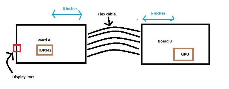
I want to use TDP142 to extend my traces for Display Port, I have two board in total and connected with a flex cable as shown in the figure below :

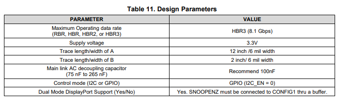
i notice that the spec mentioned :

My questions are :

1. The trace length A , is inclusive of the length of the flex cable ? (in my case)

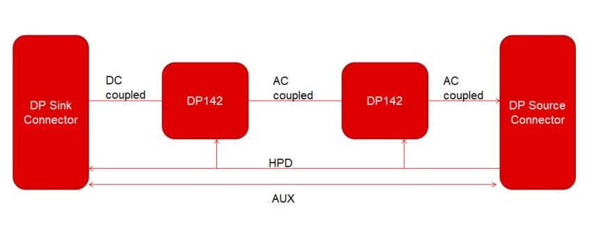
2. Can i cascade the TDP142 if i require a longer trace? 

  • Hi,

    1. No, the example assumes the GPU and the TDP142 are placed on the same board. The trace length A is the PCB trace length between the GPU and the TDP142. But depending on the loss of the flex cable, you can set the TDP142 RX equalizer to compensate for the flex cable loss.

    2. Yes, you can cascade the TDP142 if needed.

    Thanks

    David

  • Hi David, 

    Let say I have 6 mil trace width, which i will have 12 inch length for trace A . i have utilize all the 12 inch on board without including the flex cable, as describe in photo below 

    My Questions are:

    1. Is the RX equalizer able to handle this ? 

    2. is Cascaded TDP142 a must in this case.

  • Hi,

    What is the data rate and do you know how much is the loss of the 12in trace plus the flex cable?

    For example, DP1.4 is 8.1G and Nyquist frequency is 4.05GHz. Let's assume ~0.7dB/in loss for FR4 PCB material at 4.05G, the 12in loss would be ~8dB, this is still within the DP142 maximum EQ of 14.4dB. 

    If the loss of the trace, the flex cable, the flex cable connector, etc is more than 14.4dB, this is when you need to consider cascading the DP142.

    Thanks

    David

  • Hi David,

    Thanks for the reply.

    I have another question in mind, let say i want to have TDP142 cascaded (2 x TDP142).

    I wonder about the connection of pins below :

    • AUXp
    • AUXn
    • HPDIN/RSVD9
    • SNOOPENZ/RSVD8

    and is capacitor needed between TDP1's OUTDP and TSP2's INDP (the data signal lines)

    Can you provide me example of the schematics ?

    Thank you.

    Desmond

  • Desmond

    Please see below block diagram for the proposed solution.

    SNOOPENZ can be pulled high to 3.3V through a 1K to disable AUX snoop

    AUXP can be pulled down to ground through a 100k resistor. AUXN can be pulled up to 3.3V through a 100k resistor.

    Thanks

    David

  • Hi David

    Three questions

    1. If i want the AUX to be monitored by the TDP, can i connect the AUX like what HPD do ?

    2. Is TDP142 pin compatible with any of the DPv1.4 re-driver and DPv1.2 re-driver 

    3. My simulation shows I have loss of 30 dB from DP sink to DP source, do you have any recommendation ?

    Thanks you.

    -Desmond

  • Desmond

    1. The TDP142 snoops the traffic on the AUX bus for power management. It snoops native AUX writes to DisplayPort sink’s DPCD registers 0x00101 (LANE_COUNT_SET) and 0x00600 (SET_POWER_STATE). TDP142 disables/enables lanes based on value written to LANE_COUNT_SET. You could connect the AUX line like the HPD, but you have to be careful with the loading on the AUX bus to make sure the loading does not cause data corruption such that the TDP142 incorrectly disable the wrong number of lanes.

    2. Which DP1.4/1.2 redriver are you referring to?

    3. What data rate are you seeing the 30dB loss? You may need more than 2 DP142 to compensate for the 30dB loss.

    Thanks

    David 

  • David

    2. I try to search on TI products to see if any 1.2 redriver have pin compatible with it, but i do not found.

    3. i'm looking at the nyquist freq, 4.05GHz.

    Let see this scenario:

    Will it work if i set as below :

    TDP142 (B) = 14.4dB

    TDP142 (A) =  8.6dB

  • Desmond

    1. With DP142 supporting up to DP1.4 8.1G, DP142 provides backward compatibility and would work as a DP1.2 redriver as well. 

    2. How much is the loss at board B? Is it possible to put a DP142 on board B?

    Do you have a DP142 EVM that you can use to evaluate the DP142 performance with this flex cable?

    Thanks

    David

  • Hi David,

    the loss in Board B is around 15dB, cable loss is 2dB, this is checked using simulation tools. Unfortunately i do not have spaces to put a DP142 on Board B.

    I do not have DP142 EVM on hand. 

    -Desmond

  • Desmond

    15dB loss at Nyquist frequency of 4.05GHz is significant amount of loss. If we assume ~0.8dB/in loss for a FR4 material PCB, we are looking at ~18.75 inch trace on board B, does this estimation match with your proposed trace length on Board B?

    The linearity re-driver's linearity region becomes smaller as the EQ goes up. Higher EQ would also result in increasing in circuit noise. This is why I propose having the redriver on Board B to evenly distribute the loss compensation.

    Thanks

    David