A related question is a question created from another question. When the related question is created, it will be automatically linked to the original question.
If you have a related question, please click the "Ask a related question" button in the top right corner. The newly created question will be automatically linked to this question.
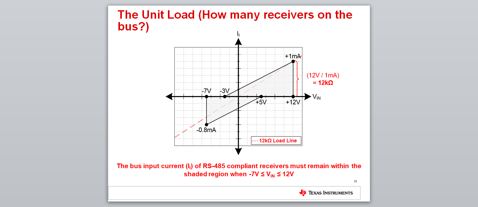
The graph can be used to understand the loading capacity of the RS485 Transciever (based on the input bias current spec)
TIA/EIA-485-A specifies that a compliant RS-485 driver must be able to drive a 1.5V differential output voltage across a common-mode range of -7V to +12V with an equivalent load of 32 1 Unit Load receivers.
1 Unit Load is equivalent to an input leakage current of 1mA at 12V, or 12kΩ.
Transceivers with higher receiver input impedance (like THVD1510), allow for more transceivers to be present on the bus.
The table below gives the unit loading, bus input leakage current, and equivalent input impedance for different receiver characteristics as an example.
The THVD1510 has 125uA Il at 12V (as shown in datasheet table 7.6) & hence cn support 256 Transceivers on Bus
If one transceiver has 5V Vcc and 0V ground, the most common mode the other node can have is +/-7V per RS485 standard. Therefore the biggest voltage difference is 5V to -7V (12V) or 0V to 7V (-7V). The maximum current can be calculated accordingly. You can ignore -3V. For the detail, please refer this app note.