This thread has been locked.

If you have a related question, please click the "Ask a related question" button in the top right corner. The newly created question will be automatically linked to this question.

TCAN4550-Q1: What is the TCAN4550 operation mode when other device intervene the BUS?

Part Number: TCAN4550-Q1
Other Parts Discussed in Thread: TCAN4550

Hiteam,

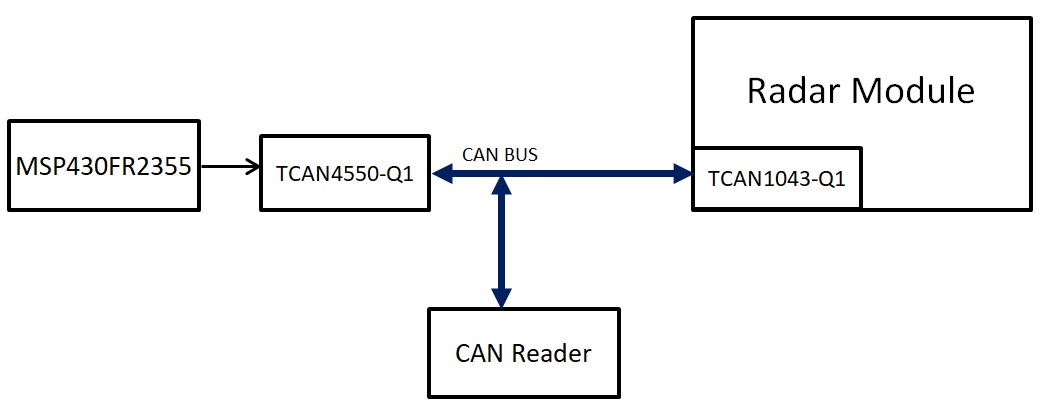
We are testing TCAN4550 in a car system. When the system power up, TCAN4550 ECU operates in the normal mode and keep sending data. At the same time when we hook up another CAN device(Radar module with CAN) on the bus, the TCAN4550 would stop working. And seems enter sleep mode. 

Could you help to clarifym with the situation described above, what would happen on TCAN4550? And how we can do in system level to deal with this scenario and make TCAN4550 can resume  

If we hook up the TCAN4550 ECU with radar module before system powering up, the interaction of TCAN4550 ECU and Radar module would function normally. 

Regards,

Alex

  • Hi Alex,

    Long time! Jonathan will help follow-up with your post.

    Do you have a  block-diagram summary to share how the system is connected & any sequencing/timing related information (you can e-mail directly).

  • Hi Alex,

    We will need to monitor and read some status registers to determine what is going on, but I have an initial thought of what might be happening based on your description.

    First, when you say "it appears to enter sleep mode" do you see SPI communication start to fail, the voltage or current levels significantly change, or through some other observable event?  The Device State Diagram in the datasheet gives the block diagram of what could cause the device to enter sleep mode, and this could come through a specific SPI write, an UVio undervoltage timer expiring, or the SWE timer expiring.   What types of observations are you making?  Are there any Interrupt bits being set as well to indicate any error conditions?

    There are also other reasons the TCAN4550 could stop communicating on the bus even though the device is not in Sleep Mode.  I think a more likely situation could be related to the device entering a Bus Off state as a result of error counters increasing past the allowable limits.  When devices are "added" to the bus, they can fundamentally change the impedance of the bus, add additional reflections and or loading that can result in timing errors, or their settings may not be compatible with the the TCAN4550's settings causing error flags to be thrown.  If the new nodes are throwing error flags correctly, or incorrectly, the TCAN4550 Transmit Error Counter (TEC) will increase to the point where it enters a protective state called Bus Off and it will stop transmitting on the bus and sets the Initialization INIT bit in the CCCR register.  The MCU will have to clear this bit before the device can transmit again.

    It is not uncommon to see some disruption on the bus when nodes are either added or removed from the bus.  There "should not" be these types of disruptions, but they do happen.

    Can you please monitor the following registers which are important for initial debug:

    0x0800 (contains MODE_SEL)

    0x0820 (Device Interrupts)

    0x0824 (MCAN Interrupts)

    0x1018 (CC Control Register which contains the INIT bit)

    0x1040 (Error Counter Register which contains the TX and RX Error Counters)

    0x1044 (Protocol Status Register which contains details on the types of errors last received)

    0x1050 (MCAN interrupts)

    Optional registers that could provide greater detail on the operation of the messages being transmitted and received:

    0x10A4 (RX FIFO 0 Status if using the RX FIFO 0)

    0x10B4 (RX FIFO 1 Status if using the RX FIFO 1)

    0x10C4 (TX FIFO/Queue Status)

    0x10CC (TX Buffer Request Pending to see if any messages are pending transmission)

    0x10D8 (TX Buffer Transmission Occurred to see if messages are being transmitted)

    0x10F4 (TX Event FIFO Status if configured)

    Once we have more details from the registers, we can better determine the root cause.

    Regards,

    Jonathan

  • Hi Ravi, It's been awhile.

    Attached the testing system block for you reference.

    Hello Jonathan, thank you for supporting.

    Customer test the system with several ways of power up sequence.With below one they faced some problem and would like to clarify the reason and prevent it in MCU coding. 

    1. First bring up TCAN4550 ECU(keep sending data), then hook up Radar(powered), and then CAN reader.

    After the operating procedure, RnD found the TCAN4550 would stop sending data and need to recycle power to recover. 

    I think it entered more likely as you said the Bus Off state due to unexpected interrupt on BUS. (Should not be the sleep mode after check the device state diagram)

    I will have RnD to dump the register you mentioned and update here.

    If it's just like you said, could you share the code and flow on how to release TCAN4550 from Bus Off state recover once this scenario happen?  

    Thanks.

    Regards,

    Alex

  • Hi Alex,

    The Bus_Off recovery sequence is defined in the ISO 11898-1:2015 CAN Standard but is summarized in the datasheet with a note following the Protocol Status Register (PSR) register description.  But I'll give a brief description but recommend reading the standard for a more complete understanding.

    Basically, the device will monitor the messages on the CAN bus and check them for protocol errors per the standard regardless of whether they are configured to accept or reject the messages and to provide an acknowledge (ACK) pulse on the message if they did not detect a error.  They could also transmit an error flag if they are not in an error passive state, but I won't get into that right now.

    If they detect an error in a received message, they will increase their RX Error Counter (REC).  If they detect an error with a message they are transmitting or another node reports an error with an error flag or the message isn't acknowledged, then the device will increase their TX Error Counter (TEC) and try to transmit the message again until it is received without error.  However if the TEC exceeds 256, it will deem itself to have a problem and then the device will stop all bus activities so that it does not interfere with "good" communication from other nodes. 

    The TCAN4550 has a "Normal Operation" mode and an "Initialization" mode which is set with the INIT bit (bit 0) of the Control Register (CCCR) (register 0x1018).  This is the same bit that must be set to '1' at the beginning of the device initialization and configuration procedure, and then set back to '0' at the end.  Since the TCAN4550 can't communicate on the bus unless it is the "normal operation" mode, setting this INIT bit '1' will prevent the device from sending any data on the CAN bus.

    In order to exit the Bus_Off state and return the device to normal operation, the MCU must set the INIT bit back to '0'.  This will allow the device to start participating in the bus activity but after that, the source of the error must have been removed in order for the device to not re-enter the Bus_Off state.  This is the part of the process better defined in the Standard, but basically good error free traffic is required for the device to completely exit the state.  Once the INIT bit is cleared by the MCU, it will wait for 129 occurrences of Bus Idle (129 * 11 consecutive recessive bits) before resume normal operation.  Each time the device monitors a sequence of 11 recessive bits (which is the minimum time between messages) then it will set the Bit0Error code in the PSR.LEC allowing the MCU to monitor the Bus_Off recovery sequence if desired and the ECR.REC is used to count these sequences.  At the end of the Bus_Off recovery sequence the Error Management Counters will be reset.

    I know that is a bit of a long explanation but I tried to prevent you from having to track down a lot of different sources.  But to summarize, the MCU basically only needs to do the following:

    1. Periodically check the BO bit (bit 7) of the Protocol Status Register (PSR) to determine if it is in the Bus_Off state.
    2. If it is in the Bus_Off state, then set the INIT bit (bit 0) of the CCCR Register (0x1018) to a value of '0'
    3. Wait for the activity on the bus to send it the required recessive bit periods to allow the device to fully exit the recovery sequence.

    I hope this has been helpful and clear.

    It sounds like the addition of the introduction of the Radar unit to the bus is causing a disruption that is causing the TCAN4550 to count Transmit Errors.  The 256 threshold is crossed very quickly if the device is configured to automatically retry the transmission of the failed messages.  Once the Radar is powered up, initialized, and ready for normal operation, the TCAN4550 will not detect transmit errors which is why they can communicate after power cycling the TCAN4550.  What they are doing is clearing the Bus_Off state by re-initializing the entire device.  However, this can be done in a more elegant way by simply recognizing the Bus_Off state and resetting the INIT bit.

    Regards,

    Jonathan