


Other Parts Discussed in Thread: ALP
Hi Team,
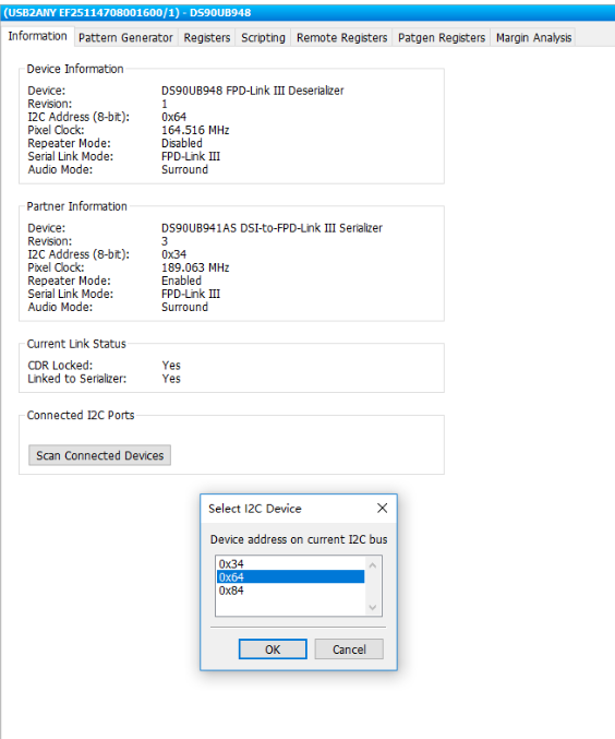
customer is using our MAP TOOLS on analysis 948.
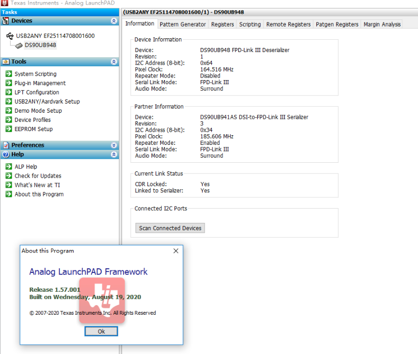
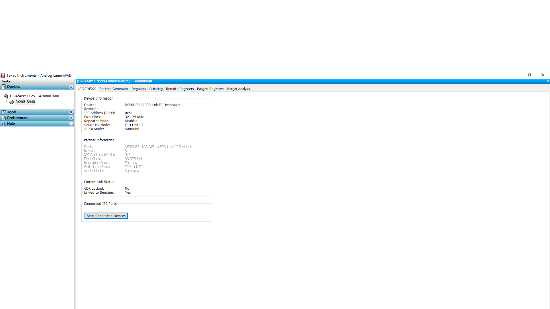
in below picture, should i select the I2C address? for now we selected 0x64
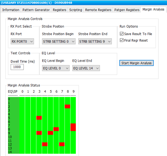
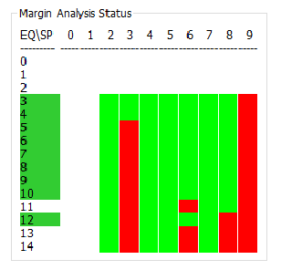
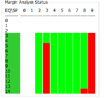
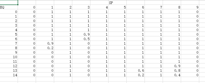
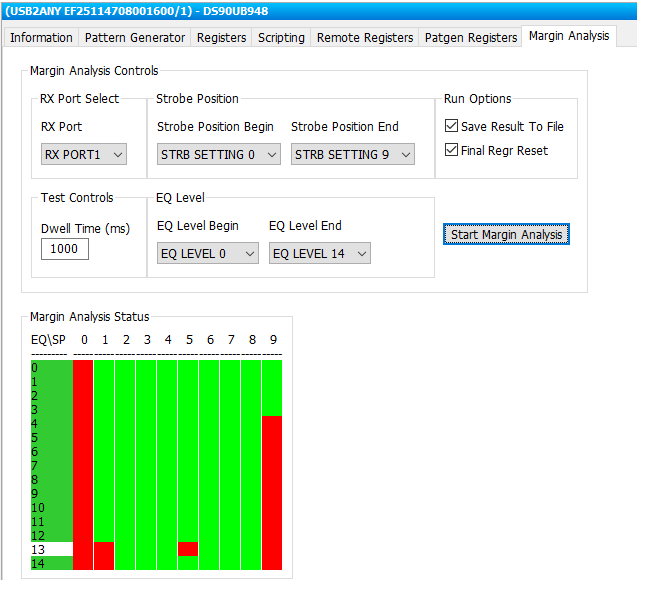
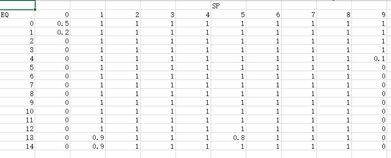
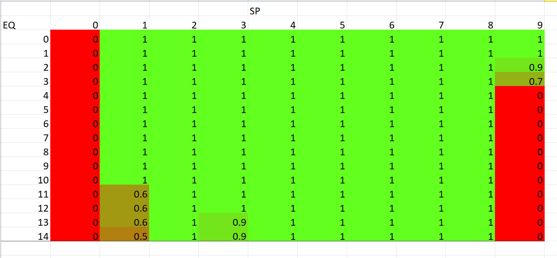
in testing result, what does the SP and EQ in Coordinate System? whether EQ is needed to set through software? How could we adjust?
i attached the testing result as follow and could you help check the result?
BR
Brandon.


