


Part Number: TCAN4550-Q1
Other Parts Discussed in Thread: TCAN4550
Hi expert,
TCAN4550-Q1 is evaluating in a customer. Now they have several question for this device, Could you help us on that? Thanks.
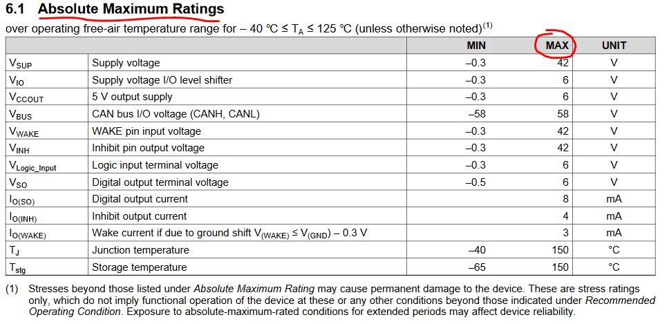
1. For the Absolute Maximum Ratings, such as max supply voltage= 42V. Is there any time limited for this data?
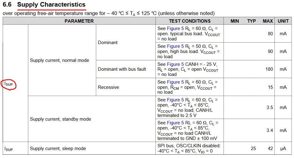
2. In page 5 of datasheet(Chapter 6.6). There is a current data. What's the supply voltage?
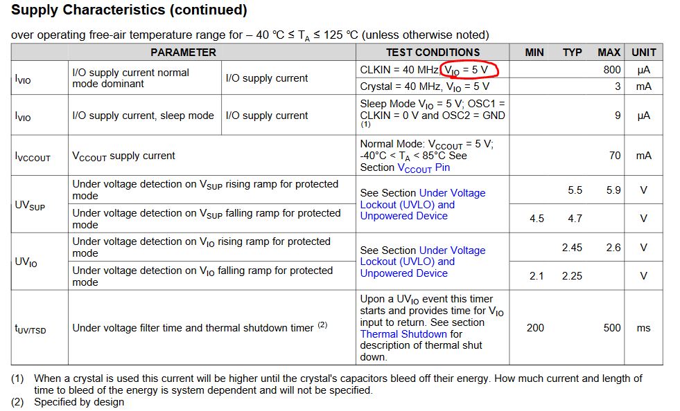
3. For the page 6 of datasheet(Chapter 6.6), when the Vio= 5V, it shows the Ivio data. Could we provide this data under Vio =3.3V?
4. When we connect a external crystal. What's the frequency requirement? Is it between 20~40Mhz? Does it have PPM over temperature requirement?
5. When INH(15)、WAKE(12)、NWKPQ(2) is unused, how to deal with it?
Best Regards
Songzhen Guo
