This thread has been locked.

If you have a related question, please click the "Ask a related question" button in the top right corner. The newly created question will be automatically linked to this question.

TLIN1022-Q1: LIN Transceiver Question

Part Number: TLIN1022-Q1


Hi

Please answer the customer's questions.

1. Current Spec for TLIN1022-Q1 LIN Bus Line is shown below.


The spec appears to indicate Current Limitation at a specific voltage, but if the node resistance is 440 ohms and the VLIN voltage is 36 volts, is it considered the maximum current value that can be dropped on the LIN1 bus?

2. Based on the circuit below, I think the current limit of LIN Bus Line will be determined by the R45/R46 value and the resistance value of the node, is it correct?


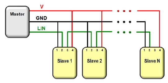
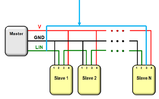
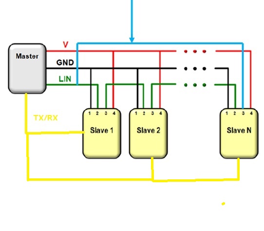
3. When 14 LIN Actors are connected in series, can I check if there is a possibility of a problem with LIN communication?

4. How many nodes are recommended per LIN line of TLIN1022-Q1?
If there is no recommended node quantity, please check the maximum number of nodes available.

  • Cho,

    Thank you for bringing your questions to E2E.

    1. This current limitation range is defined by the LIN specification. A LIN node must be able to sink at least 40mA, and the maximum current flowing in to the node must not exceed 200mA in DC conditions. VSUP = 36V  and Rmeas = 440 ohms were used to emulate the "worst" case (36V being the highest VSUP operating voltage) in our test to validate that the current-limiting was working correctly on the transceiver. 
    2. Yes, but there is also internal current-limiting on the transceiver in case a short occurs during a dominant transmission on the bus.
    3. These are similar specs of a LIN transceiver, so I don't see any issues since LIN clusters can be up to 16 nodes. How are these connected in series?
    4. In any LIN application, per the LIN standard, LIN buses are able to hold up to 16 nodes, 1 controller and 15 responders. To adhere to the LIN standard the LIN transceiver must be able to drive with 15 other nodes on the LIN bus. So, each LIN line is capable of being on a LIN bus with 15 other nodes, 16 total.

    Regards,

  • Hi Eric,

    Thank you for your reply.

    The 14 series connections are connected as follows.

  • Hi Eric,

    Please check if there is any problem with the 14 serial connections of the above blocks.

    We believe there is no problem because up to 16 nodes are possible, but please reply.

  • Cho,

    The transceivers will function properly in this configuration up to 16 nodes, correct. Is this daisy chain approach also using redundant TXD and RXD connections on the controller side of the transceivers?

    Regards,

  • Eric 

    The customer's answer is as follows.
    In the last Slave Node, the communication line ends and does not connect directly to the Master (Controller).

    Please check if the question I understand is correct.
    Should I check if the yellow TX/RX shown below is connected to Slave1 and 2~N as well?

  • Hi Eric

    I would like you to give me your opinion on the above reply.

    Additional questions:
    Will there be a problem if the main ground of the system and the LIN communication ground are tied to the same ground when applying TLIN1022-Q1?
    It is not possible to determine if isolation is required when applied to car vehicle actuators.

  • Cho,

    I just want to make sure I understand the TXD and RXD connections in the LIN cluster. Since the signals are being daisy chained between two LIN bus pins on the TLIN1022, they will transmit and return data to two separate TXD and RXD pins (TXD1 - LIN1 - RXD1, TXD2 - LIN2 - RXD2). I just want to understand how the customer is connecting the TXD and RXD pins to their respective controllers.

    Connecting the main system ground to the LIN communication GND should not be a problem. The TLIN1022-Q1 can handle ground offset as long as that offset does not place VSUP below the under voltage threshold. Is this what the customer is asking?

    Regards,