This thread has been locked.

If you have a related question, please click the "Ask a related question" button in the top right corner. The newly created question will be automatically linked to this question.

TCAN4550: Problem with sending back ACK data, timing isue and GLOBALERR

Part Number: TCAN4550


Hi,

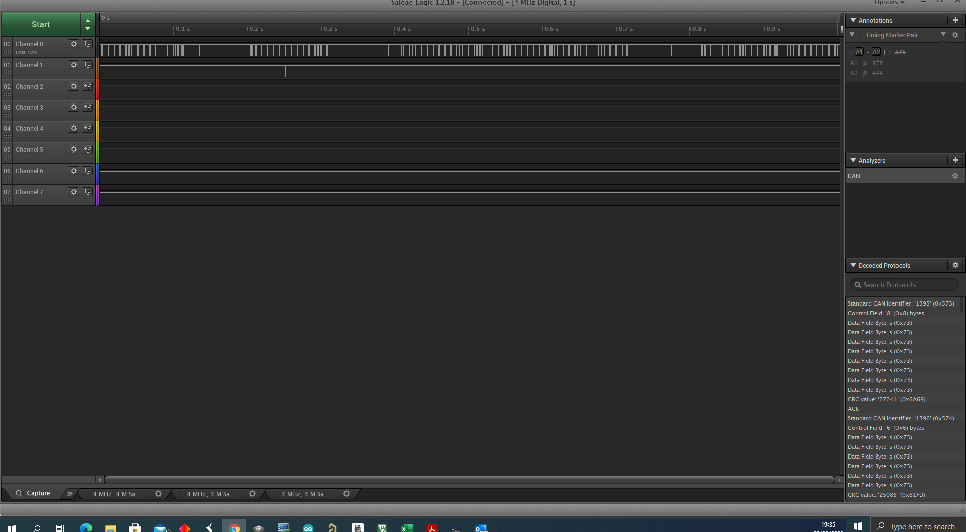
We are using TCAN4550 for our project on a custom board. Setup is like this, one board is sending data, another is listening.

So the board which is sending expects ACK data. But there lies an issue. When the receiver gets the data it should send ACK back immediately but it usually sends it in the range of 90-100ms which is too much.

So communication is working perfectly, if I look at register status everything is clear except GLOBALERR, i don't know if this has anything to do with it. 

Code is created based on your example. (TCAN4550_DEMO).

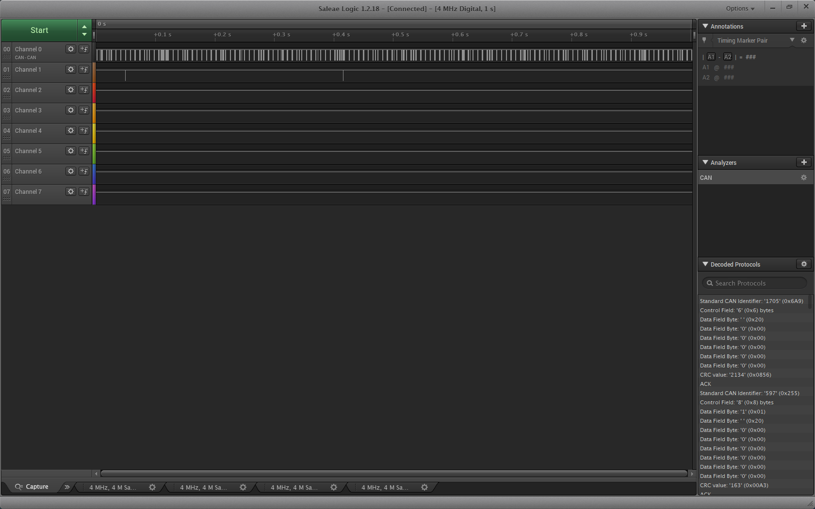
if (MsgHeader.ID == 0x6A9) // Example of how you can do an action based off a received address
{
     if(rx_data[0] == 0x10)
     {
          speed = ( rx_data[3]  << 8 ) | rx_data[2];
          header.ID = 0x255;
          tx_data[0] = 0x01;
          tx_data[1] = 0x10;
          tx_data[2] = 0x00;
          tx_data[3] = 0x00;
          tx_data[4] = 0x00;
          tx_data[5] = 0x00;
          tx_data[6] = 0x00;
          tx_data[7] = 0x00;
          

         TCAN4x5x_MCAN_WriteTXBuffer(0, &header, tx_data); // This line writes the tx_data and header to TX FIFO 1
         TCAN4x5x_MCAN_TransmitBufferContents(0); // Request that TX Buffer 1 be transmitted
      }

}

Can you please help me why is there such a delay, and what means GLOBALLERR?

Thank you

Seba.

  • Hi Seba,

    As defined in the CAN Standards, the receiver is to send an ACK pulse immediately following the completion of a message on the bus coming from a different transmitting node.  This must be within the immediate bit periods following the message and if the receiving node does not send an ACK pulse on the bus, then the transmitting node will consider that a failed message, increase the transmit error counter, and then try to send the message again.  The receiver node will also increase its receive error counter.

    In the TCAN4550, the CAN FD controller handles this ACK pulse in hardware if it has received the message error free and it is not possible for there to be a 90-100mS delay.  Perhaps we are using the ACK term to mean two different things.  Do you expect the receiving node to transmit a message back to the original transmitting node as an "Acknowledgement" that it received a message?  If so then a delay of 90-100mS could be understood and would be a result of the MCU firmware routine.

    The GLOBALERR is the Logical OR of all faults in registers 0x0820 and 0x0824, therefore if it is being set then there is another fault bit being set as well.  Can you read both registers 0x0820 and 0x0824 so that we can see which fault is setting the GLOBALERR flag?

    Regards,

    Jonathan

  • Hi Jonathan

    Thank you for a very quick reply.  I interpret ACK completely wrong, what I meant with this is the message which is broadcasted back to the transmitter. Sorry for misunderstanding. Like you suggested, I also think it is a firmware related issue. Do you maybe have some tips, how to lower this time? Maybe with filters?

    About GLOBALERR interrupt I looked at all the registers and you are right M_CAN_INT is triggered (0x01), the reason is that a new message has come into the buffer.
    Regards.
    Sebastijan Cvirn
  • Hi Sebastijan,

    I thought that ACK message was what you meant, and it looks like your system is generally working properly.  There is probably some room for improvement on the response delay but this is unfortunately one of the few areas of the TCAN4550 that can be difficult to manage due to the SPI interface.

    Since I don't have any specific details on your system requirements and architecture, I can only speak in general terms.  But here are some thoughts to consider:

    1. Are you using a hardware interrupt routine, or are you polling the status and interrupt registers to determine when a new message has been received?
      1. If you are polling the registers, you should consider using a hardware interrupt pin so reduce the SPI bus overhead and allow an immediate response to be triggered as soon as the interrupt pin is set.
      2. If you are already using an interrupt signal, consider using one of the GPIO1 or GPO2 pins as a dedicated MCAN Message Interrupt line which will allow you separate the RX Messages from the rest of the possible interrupt flags.  This can allow your Interrupt Routine to immediately start reading the RX Message instead of spending time decoding the Interrupt register value and determine the cause of the interrupt flag which could come from numerous unrelated flags.
    2. The most significant delay will come from the SPI Overhead and time required to read and write data into the TCAN4550.
      1. Use the fastest SPI frequency possible.  The only limitation is that it must be less than 18Mhz, or less than the crystal frequency by about 1Mhz if a clock frequency less than 20Mhz is used.  This is to ensure that the data can pass between the Digital core clock domain and SPI clock domain without error.  But reducing the SPI bit time will reduce the overall delay by a proportional amount.
      2. Use SPI Burst Reads and Writes to read and write from the RX/TX Message buffers.  If you are reading each 32bit word one at a time, half of each SPI transaction is the address and straight overhead that adds up to a significant delay.  However, if you do a Burst Read/Write, you only pass the initial start address and overhead bits on the first transaction and the rest of the transaction is only data related.
    3. Is the receiving node configured to echo the message back to the sending node, or does it simply need to send an acknowledgement message without sending any specific data payload that must be generated at the time of request or after the original message has been received?
      1. If an acknowledgement message is all that is needed, you could have a specific message already stored in a specific TX Buffer and as soon as you see the interrupt flag from the received message, the MCU can immediately issue a transmit request to this specific TX Buffer and send a message back on the bus.  This is possibly the fastest way a response is possible, but the message data payload has to be preloaded in the TX Buffer. But this eliminates all of the SPI bus overhead and the time needed to read the RX Buffer or RX FIFO, process the message in the MCU, and then reload a new message in a TX Buffer and then issue a send request.
      2. If you need to pass a meaningful data payload in the response message, then use the SPI Burst Mode to fill the buffers and consider using the smallest possible data payload.
      3. Reduce as much overhead in the MCU code to allow the fastest response and processing of the received message and sending the response message.

    4. This probably doesn't apply in your two board system, but in larger systems you may get delays due to the message Identifier chosen.  In CAN the messages are transmitted in a priority system with the lowest ID receiving the highest priority.  If there is a lot of traffic on the bus, you should use the lowest possible ID value to ensure it is given the appropriate priority level in the system.

    I hope this gives you some ideas on how to optimize your system for a faster response.

    Regards,

    Jonathan

  • Hi Jonathan,

    Thank you for your answer and tips. I will describe system a little bit:

    We are using architecture as master and other nodes are slaves. Master is sending messages(asking other nodes for data) and expect acknowledgement message within 100ms. Data is send from master roughly every 8-10ms. TCAN4550 usually respond within 1m, which is more than perfect. I am using external interrupt and then reading data, same practice as you have in example. But as you can se there are some gaps between data (bottom picture). I was able to shrink amount of this gaps that i lower this parameter to 1 or 2:

    "MRAMConfiguration.Rx0NumElements = 1; // RX0 Number of elements"

    I was also try to setup filter but i was not successful can you help me with that?

    i want to have filter to se only two messages: ID-0x6A8 and ID-0x6A9

    Question about filter - if message is outside filter does it trigger interrupt?

    Zoomed picture: you can see to stripes together first is request and second is answer, in the middle you can see big gap which i want to get rid off.

    Regards.

    Sebastijan

  • Hi Sebastijan,

    There are a couple of different ways you could structure your filters, but here is one suggestion. I have not been able to test it out in hardware myself, but I can do so if needed. However let’s see if this is enough to get you moving in the right direction.

    For additional information on the Filters there is a pretty good write up on them in the TCAN45xx Software User’s Guide.

    https://www.ti.com/lit/ug/sllu270/sllu270.pdf

    Section 4.2 covers the Message RAM configuration and section 4.2.3 discusses the 11-bit Standard ID filters (SID Filters) which I think is what you want.

    More information on the Bosch M_CAN CAN FD Controller can be found on Bosch’s website at the following link. It was not practical to duplicate all of the information about M_CAN in the TCAN4550 datasheet especially since it is very well documented by Bosch. This User’s Guide is a great supplemental resource to the TCAN4550 Datasheet and Software User’s Guide.
    https://www.bosch-semiconductors.com/ip-modules/can-ip-modules/m-can/

    But generally speaking you will need to create a Standard ID Filter Element which is a 32-bit word and write that to the SID Filter Element section of your MRAM configuration. The details of a SID Filter Element are as follows:

    SID Filter Element

    Name

    Description

    Bits

    SFT

    Standard Filter Type

    [31:30]

    SFEC

    Standard Filter Element Configuration

    [29:27]

    SFID1

    Standard Filter ID 1

    [26:16]

    Reserved

    Reserved

    [15:11]

    SFID2

    Standard Filter ID 2

    [10:0]

    SFT

    Value (Binary)

    Description

    2’b00

    Range Filter: Accepts all IDs from SFID1 to SFID2

    2’b01

    Dual ID Filter: Matches both SFID1 and SFID2 (ID must be exact match)

    2’b10

    Classic Filter: SFID1 is the filter, SFID2 is the mask. 0 in the mask corresponds to “don’t care”. See below for more information

    2’b11

    Filter Element Disabled: This filter will match nothing.

    SFEC

    Value (Binary)

    Description

    3’b000

    Disable filter element. Does nothing, matches nothing

    3’b001

    Store in Rx FIFO 0

    3’b010

    Store in Rx FIFO 1

    3’b011

    Reject message. No interrupt will be set, and message is simply ignored.

    3’b100

    Set as priority message (interrupt), message storage location depends on other filters or default behavior

    3’b101

    Set as priority (interrupt) and store in FIFO 0

    3’b110

    Set as priority (interrupt) and store in FIFO 1

    3’b111

    Store into Rx Buffer or as debug message. If this is used, SFT is ignored and SFID1 is the filter. SFID2[10:9] describes where to store message, SFID2[5:0] describes which Rx Buffer to put the message (must be within the Rx Buffer configuration)

    Final SID Filter Element

    Name

    Description

    Bits

    Value

    SFT

    Standard Filter Type

    [31:30]

    2’b00

    SFEC

    Standard Filter Element Configuration

    [29:27]

    3’b101

    SFID1

    Standard Filter ID 1

    [26:16]

    11’b11010101000

    Reserved

    Reserved

    [15:11]

    5’b00000

    SFID2

    Standard Filter ID 2

    [10:0]

    11’b11010101001

    This will make your Final SID Filter Element = 0x2EA806A9

    Now you will have to configure the Standard ID Filter Configuration (SIDFC) register with the number of SID Filter elements and the Start Address of the standard Message ID filter list (32-bit word address) so that M_CAN knows where to look for the start of the SID Filter List when it receives a message and how many filters are in the list. The search always starts at the first SID Filter Element in the list so if you have more than one filters, you should sequence them in a prioritized manner in MRAM to speed up the filter process. The SIDFC Register configuration details are as follows:

    Standard ID Filter Configuration (address 0x1084)

    Name

    Description

    Bits

    Reserved

    Reserved

    [31:24]

    LSS[7:0]

    List Size Standard

    [23:16]

    FLSSA[15:2]

    Filter List Standard Start Address

    [15:2]

    Reserved

    Reserved

    [1:0]


    LSS[7:0] List Size Standard

    Value (Binary)

    Description

    0

    No standard Message ID filter

    1-128

    Number of standard Message ID filter elements

    >128

    Values greater than 128 are interpreted as 128

    FLSS[15:2] Filter List Standard Start Address

    Value (Binary)

    Description

    <Determined by User when configuring MRAM Address Space>

    Start address of standard Message ID filter list (32-bit word address)


    If you are using a variant of the TCAN4550_DEMO code, the following structs are available to hold the settings:


    TCAN4x5x_SID_SFEC_Values

    TCAN4x5x_SID_SFT_Values

    TCAN4x5x_MRAM_Config

    TCAN4x5x_MCAN_SID_Filter


    typedef enum

    {

       //! Disabled filter. This filter will do nothing if it matches a packet

       TCAN4x5x_SID_SFEC_DISABLED         = 0x0,


       //! Store in RX FIFO 0 if the filter matches the incoming message

       TCAN4x5x_SID_SFEC_STORERX0         = 0x1,


       //! Store in RX FIFO 1 if the filter matches the incoming message

       TCAN4x5x_SID_SFEC_STORERX1         = 0x2,


       //! Reject the packet (do not store, do not notify MCU) if the filter matches the incoming message

       TCAN4x5x_SID_SFEC_REJECTMATCH     = 0x3,


       //! Store in default location but set a high priority message interrupt if the filter matches the incoming message

       TCAN4x5x_SID_SFEC_PRIORITY         = 0x4,


       //! Store in RX FIFO 0 and set a high priority message interrupt if the filter matches the incoming message

       TCAN4x5x_SID_SFEC_PRIORITYSTORERX0 = 0x5,


       //! Store in RX FIFO 1 and set a high priority message interrupt if the filter matches the incoming message

       TCAN4x5x_SID_SFEC_PRIORITYSTORERX1 = 0x6,


       //! Store in RX Buffer for debug if the filter matches the incoming message. SFT is ignored if this is selected.

       TCAN4x5x_SID_SFEC_STORERXBUFORDEBUG = 0x7

    } TCAN4x5x_SID_SFEC_Values;


    typedef enum

    {

       //! Disabled filter. This filter will match nothing

       TCAN4x5x_SID_SFT_DISABLED           = 0x3,


       //! Classic filter with SFID1 as the ID to match, and SFID2 as the bit mask that applies to SFID1

       TCAN4x5x_SID_SFT_CLASSIC           = 0x2,


       //! Dual ID filter, where both SFID1 and SFID2 hold IDs that can match (must match exactly)

       TCAN4x5x_SID_SFT_DUALID             = 0x1,


       //! Range Filter. SFID1 holds the start address, and SFID2 holds the end address. Any address in between will match

       TCAN4x5x_SID_SFT_RANGE             = 0x0

    } TCAN4x5x_SID_SFT_Values;


    You should be able to simply modify the TCAN4x5x_MCAN_SID_Filter element with your new values. This is the code as written in the DEMO code in the main.c file:

           /* Setup filters, this filter will mark any message with ID 0x055 as a priority message */

           TCAN4x5x_MCAN_SID_Filter SID_ID = {0};

           SID_ID.SFT = TCAN4x5x_SID_SFT_CLASSIC;                                   // SFT: Standard filter type. Configured as a classic filter

           SID_ID.SFEC = TCAN4x5x_SID_SFEC_PRIORITYSTORERX0;                  // Standard filter element configuration, store it in RX fifo 0 as a priority message

           SID_ID.SFID1 = 0x055;                                                                 // SFID1 (Classic mode Filter)

           SID_ID.SFID2 = 0x7FF;                                                                 // SFID2 (Classic mode Mask)

           TCAN4x5x_MCAN_WriteSIDFilter(0, &SID_ID);                                // Write to the MRAM

    You should be able to modify it as follows for your desired settings:

           /* Setup filters, this filter will mark any message with ID 0x6A8 or 0x6A9 as a priority message */

           TCAN4x5x_MCAN_SID_Filter SID_ID = {0};

           SID_ID.SFT = TCAN4x5x_SID_SFT_RANGE;                                     // SFT: Range Filter type. Configured as a range filter

           SID_ID.SFEC = TCAN4x5x_SID_SFEC_PRIORITYSTORERX0;                  // Standard filter element configuration, store it in RX fifo 0 as a priority message

           SID_ID.SFID1 = 0xA68;                                                                 // SFID1 (Range Filter Start ID)

           SID_ID.SFID2 = 0xA69;                                                                 // SFID2 (Range Filter End ID)

           TCAN4x5x_MCAN_WriteSIDFilter(0, &SID_ID);                                // Write to the MRAM


    The code will configure the SID Filter Elements as part of the following function:


    TCAN4x5x_MRAM_Configure(TCAN4x5x_MRAM_Config *MRAMConfig)

    I hope this is clear and helpful. If you still have questions, please let me know.

    Regards,

    Jonathan

  • Hi Jonathan,

    Thank you for detailed explanation.

    I tried your suggestion and i think i checked everything three times but its not working as expected.

    My settings for filters are:

    /* Configure the default CAN packet filtering settings */
    TCAN4x5x_MCAN_Global_Filter_Configuration gfc = {0};
    gfc.RRFE = 1; // Reject remote frames (TCAN4x5x doesn't support this)
    gfc.RRFS = 1; // Reject remote frames (TCAN4x5x doesn't support this)
    gfc.ANFE = TCAN4x5x_GFC_ACCEPT_INTO_RXFIFO0; // Default behavior if incoming message doesn't match a filter is to accept into RXFIO0 for extended ID messages (29 bit IDs)
    gfc.ANFS = TCAN4x5x_GFC_ACCEPT_INTO_RXFIFO0; // Default behavior if incoming message doesn't match a filter is to accept into RXFIO0 for standard ID messages (11 bit IDs)

    TCAN4x5x_MCAN_SID_Filter SID_ID = {0};
    SID_ID.SFT = TCAN4x5x_SID_SFT_RANGE; // SFT: Standard filter type. Configured as a classic filter
    SID_ID.SFEC = TCAN4x5x_SID_SFEC_PRIORITYSTORERX0; // Standard filter element configuration, store it in RX fifo 0 as a priority message
    SID_ID.SFID1 = 0x6A8; // SFID1 (Classic mode Filter)
    SID_ID.SFID2 = 0x6A9; // SFID2 (Classic mode Mask)
    TCAN4x5x_MCAN_WriteSIDFilter(0, &SID_ID); // Write to the MRAM

    TCAN4x5x_MCAN_EnableProtectedRegisters(); // Start by making protected registers accessible
    TCAN4x5x_MCAN_ConfigureCCCRRegister(&cccrConfig); // Enable FD mode and Bit rate switching
    TCAN4x5x_MCAN_ConfigureGlobalFilter(&gfc); // Configure the global filter configuration (Default CAN message behavior)
    TCAN4x5x_MCAN_ConfigureNominalTiming_Simple(&TCANNomTiming); // Setup nominal/arbitration bit timing
    TCAN4x5x_MCAN_ConfigureDataTiming_Simple(&TCANDataTiming); // Setup CAN FD timing
    TCAN4x5x_MRAM_Clear(); // Clear all of MRAM (Writes 0's to all of it)
    TCAN4x5x_MRAM_Configure(&MRAMConfiguration); // Set up the applicable registers related to MRAM configuration
    TCAN4x5x_MCAN_DisableProtectedRegisters(); // Disable protected write and take device out of INIT mode

    At firs i thought that i did not set something right, but then i went to debugger and start observing registers.

    i was looking for that SID Element that you suggested:

    This will make your Final SID Filter Element = 0x2EA806A9

    Here is picture from debuger.

    As you can see everything is correct.

    But when i start to observe system and messages, the system jumps to interrupt rutine when unwanted message comes, look the picture.

    RXMsgHeader.ID == PDR (PDR = 0x6A8) 

    RXMsgHeader.ID == 0x560 (unwanted message)

    I don't know exactly what am i doing wrong, do you have a clue maybe? 

    Regards.

    Sebastijan

  • Hi Sebastijan,

    I think the ANFS[1:0] and ANFE[1:0] bit fields may be set wrong in the Global Filter Configuration address 0x1080.  By default they are set to 2'b00 which means they will accept any message frame that does not match a filter and place them into RX FIFO 0.  If you accept a filtered message and store it into RX FIFO 0 while accepting all non-matching frames and storing them into RX FIFO 0, you are still going to receive every message and get an interrupt for each one.

    You can change these bit fields to either 2'b10 or 2'b11 which will reject any message frame that does not match a filter.  Or you can set it up such that filtered messages go into one storage location such as RX FIFO 0 or a RX Buffer which could be thought of as high priority messages, and any non-matching messages could be directed to a different location such as RX FIFO 1. 

    Try checking the GFC register and make sure that ANFS and ANFE are set to "Reject" non-matching messages and try your test again. 

    Regards,

    Jonathan

  • Hi Jonathan,

    Thank you very very much for answer. It helped a lot, but i have to add little change.

    I set registers as you advise:

    gfc.ANFE = TCAN4x5x_GFC_REJECT;
    gfc.ANFS = TCAN4x5x_GFC_REJECT;

    But problem was also in this settings:

    MRAMConfiguration.SIDNumElements = 2;
    MRAMConfiguration.XIDNumElements = 0;

    I had to change this XIDNumElements from zero to 1, if it is set to zero filtering is not working.

    MRAMConfiguration.SIDNumElements = 2;
    MRAMConfiguration.XIDNumElements = 1;

    Here is the result its amazing how quick it is.


    As you can see on picture there is no gaps, like before. Now i can even increase FIFO to 5 elements and it does not effect speed.

    Now i have got last question.

    The system will grow with development and of course new things will be send over can. Now can accept only two messages and filter is set that it is allowing  messages between SFID1 and SFID2. If i want to set filter with 5 or 10 elements with totally different IDs, how can i set this properly?

    Sorry for a lot of questions but product will go to mass production next year and it have to work properly:)

    Regards

    Seba

  • Hi Sebastijan,

    I am glad you have made some good progress and good catch on the XID element settings.  Since you had only been asking about 11-bit ID's I only focused on SIDs, but the concepts are the same for both SID and XID Filters.

    When it comes to additional filters, you have some options that are available to you depending on how many you need and what ID's you want to filter.  The TCAN4550 uses the M_CAN CAN FD controller developed by Bosch and you can find the M_CAN User Manual on Bosch's website that explains the M_CAN features in more detail.  The TCAN4550 contains the register map and only the most relevant information, but it was not practical to completely duplicate the information already documented by Bosch and the M_CAN User manual should be used as a supplement to the TCAN4550 datasheet.  You can find it at the following link.  The Filter Elements are discussed in sections 2.4.5 and 2.4.6.

    https://www.bosch-semiconductors.com/media/ip_modules/pdf_2/m_can/mcan_users_manual_v330.pdf

    You can have up to 128 SID Filter Elements, and up to 64 XID Filter Elements and you can always just create as many filters as you need to accommodate all of the ID's you need to filter.  When a message is received the device will start evaluating the message with the first filter stored in memory, and then continue with all of the filters in the list until one of the filter matches, or there are no mare filters.  If one of the filters matches, then the device will store or reject the messages based on the filter settings.  If no filter matches, the device will store or reject the message based on the GFC non-matching frame settings which we have previously discussed.

    There are also three different filter types that you can use. 

    1. Range Filter from ID1 to ID2, where ID2 is >= ID1

    2. Dual ID filter for ID1 or ID2

    3. Classic Filter where ID1 = filter and ID2 = mask.  This is useful if your messages have common bits, such as a range of messages that have some common bits, but are not necessarily in a consecutive range. 

    I had suggested a Range filter for you since you had consecutive ID's, but I could have used the Dual ID, or two Classic filters to accomplish the same filtering.  When you need to scale your design, I would suggest that you evaluate the ID's to determine which filter types will be the most appropriate.  You can also use a different filter type for each filter, so you can have some Range, Dual and Classic filters as needed.  You can also use filters to store messages into separate locations such as RX FIFO 0, RX FIFO 1, and RX Buffers if it is better to organize and or prioritize the reading of some messages over others.  For example, if you had some higher priority messages, you could always filter them into RX FIFO 0, and then other lower priority messages could be filtered into RX FIFO1.  This would allow you to ensure that if you received new messages into RX FIFO 0 and 1, your MCU could always read back the higher priority messages in RX FIFO 0 before it read back the lower priority messages in RX FIFO 1.  This is just an example of what could be done.  However, you can keep it simple and simply have everything filtered into a single RX FIFO as you are doing.

    I hope this is clear.

    Regards,

    Jonathan

  • Hi Jonathan,

    Thank you for all the help!

    Regards.

    Seba

  • You're welcome.  Feel free to reach back out if you have additional questions.  Good Luck in your development!

    Best Regards,

    Jonathan