This thread has been locked.

If you have a related question, please click the "Ask a related question" button in the top right corner. The newly created question will be automatically linked to this question.

TPS25750: Tolerance of Power path

Part Number: TPS25750
Other Parts Discussed in Thread: TPS65987D

Hello,

- 1 -

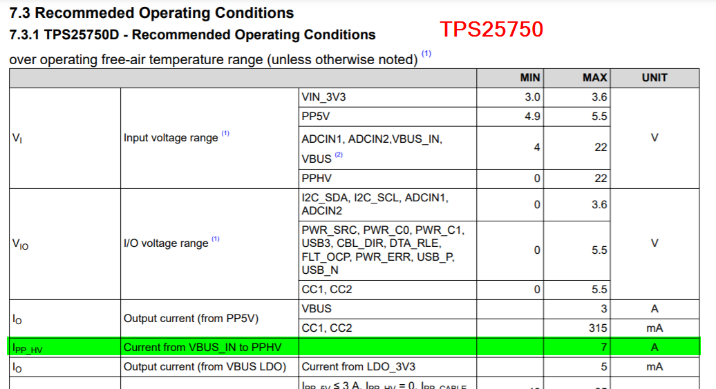
According to datasheet of TPS25750, Absolute max for sink current is defined as "7A" (7.1.2 TPS25750D - Absolute Maximum Ratings).

On the other hand, "7A" is also defined in section 7.3.1 TPS25750D - Recommended Operating Conditions of "IPP_HV" parameter.

I wonder it is ok that recommended current is same as absolute current.

Could you confirm ?

- 2 -

As I described above, "7A" is also defined in section 7.3.1 TPS25750D - Recommended Operating Conditions of "IPP_HV" parameter.

I'm not sure which usecase "7A" is used. (USB PD is defined up to 5A on current specification(Rev PD3.0).)

Which usecase do you assume ?

BR,

  • Hello Ryuuichi,

    Yes it is okay that the recommended and absolute maximum conditions line up because the FET can handle up to 10A if the current spikes are pulses with durations ≤ 100 µs and have a duty-cycle ≤ 1%. The datasheet is just stating to not exceed a continuous current draw greater than 7A. 

    As far as the PD spec, some customers actually supply more than 5A while in a user alternate mode which the spec allows for. However, I only know of 1 customer that does this, so your system should not get to the 7A limit since you will not be able to enter into the specific user alternate mode for the devices that can support >5A. Do not need to worry about this

  • Hello Adam-san,

    Thank you for your reply.

    - 1 -

    >Yes it is okay that the recommended and absolute maximum conditions line up because the FET can handle up to 10A if the current spikes are pulses with durations ≤ 100 µs and have a duty-cycle ≤ 1%.

    I think that this spec is same meaning as following spec which is described in TPS65987D.

    * "IOCP" PP_HV Quick Response Current Limit

    This is also defined as 10A.

    Previously, I saw following thread about tolerance of current.

    e2e.ti.com/.../3437189

    You described "The high voltage sink FET is rated to a higher current than the TPS65987D, so sinking at 5A should not be an issue." for TPS25750 in above thread.

    However, I wonder whether above sentence is correct from your reply. Because, "IOCP" which is described TPS65987D defined as over current protection. On the other hand, 10A is defined as "Absolute max" in TPS25750. (I think that this means OCP is less than this spec.)

    IOCC is defined in TPS65987D. When user set this to "min5.697 Typ6.330 Max6.963"(I'm not sure how user can set this setting. Becasue there is no information about this both datasheet and TRM.),  it seems that this is similar to 7A(continuous current) of TPS25750.

    Question : Which spec did you compare to say  "The high voltage sink FET is rated to a higher current than the TPS65987D, so sinking at 5A should not be an issue." ?

    - 2 -

    >As far as the PD spec, some customers actually supply more than 5A while in a user alternate mode which the spec allows for.

    I'm sorry I'm not sure "user alternate mode".

    Does it mean unique specification which do not comply with USB PD specification ?

    Best Regards,

  • You can see the difference in the datasheets. The TPS65987D is recommended to only support a max of 5A while the TPS25750 can support a max of 7A when using the PPHV to VBUS_IN power path

    As far as the user alternate mode here is a brief definition from the spec. You do not need to worry about this though for your application.

  • Adam-san,

    For 1 :

    I understood souce of "The high voltage sink FET is rated to a higher current than the TPS65987D, so sinking at 5A should not be an issue.".

    For 2 :

    Thank you for your reply.

    I also understood "user alternate mode" by refering following document.

    https://www.tij.co.jp/jp/lit/an/slvae16a/slvae16a.pdf

    Best Regards,