This thread has been locked.

If you have a related question, please click the "Ask a related question" button in the top right corner. The newly created question will be automatically linked to this question.

TPS25810: TPS25810 IN1&IN2 and AUX application question.

Part Number: TPS25810

Hi Team,

could you please comment on the questions shown as below:

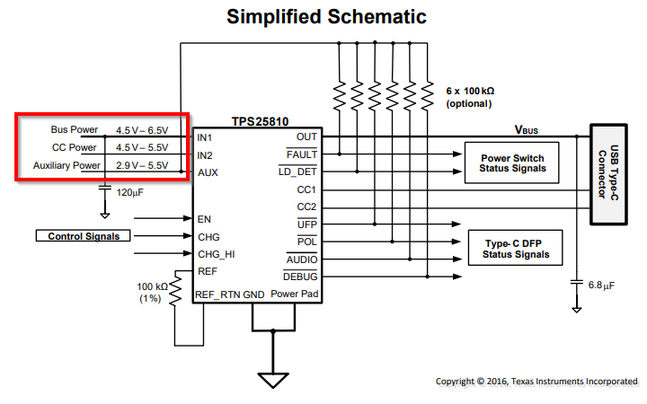
1. Does the AUX can connect on the 3.3V power rail or only can connect to 5V?

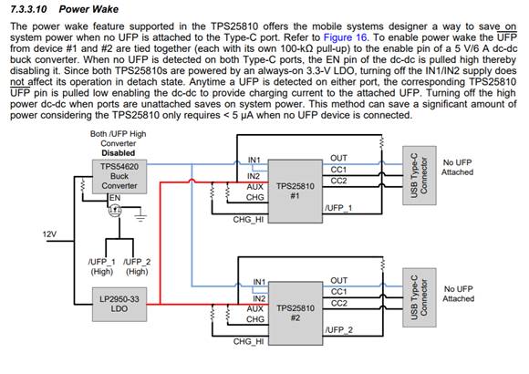
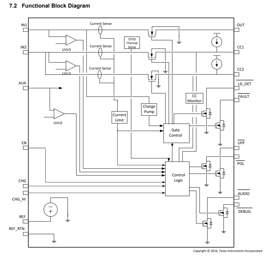
2. Could you help double check if TPS25810 can disable OUTPUT power when there isn’t device attach even power on IN1&IN2&AUX?

3. Because this device have integrated a MOSFET on VBUS, so does this means the chip itself can control the output of VBUS? There is no need to close IN1 and IN2 to achieve energy saving management.

4. If AUX supplies power to CC1 and CC2, what is the current of the entire AUX?

 B.R.

 Zhizhao

  • Hello,

    I've assigned this issue to the relevant expert who will get back to you shortly.

    Thank you,

    Hari

  • Hi Zhizhao,

    1. AUX can support a minimum of 2.9V and a maximum of 5.5V. It will be able to support a 3.3V rail. 

    2. If the device does not detect anything on the CC lines, it will not supply output power. Check out Table 2 in the datasheet for more information on scenarios where the TPS25810 will provide output power. 

    3. IN1 and IN2 have separate functions. IN1 is connected to OUT by the internal power FET and serves the supply for the Type-C charging current. IN2 is the supply for VCONN and ties directly between the VCONN power switch on its input and CC1 or CC2 on its output. AUX or auxiliary input supply provides power to the chip. Check out 7.3.3.1 for more information on IN1, IN2, and AUX. 

    4. AUX provides power to the chip. IN2 provides power to the CC pins. The current on the CC pins depends on if the cable is supplying VCONN or not. When supplying VCONN, the max current is 250mA.

    Thanks,

    Emma

  • Hi Emma,

    Thanks for your reply and I wonder if the IN1 and IN2 are power off , does the AUX connect to the CC1 and CC2 and supply the CC1 and CC2? Thanks!

    B.R.

    Lucas

  • Hi Lucas,

    CC1 and CC2 are connected and powered by IN2. 

    Regards,

    Emma

  • Hi Emma, 

    Does that means when power off IN1 and IN2, the AUX can not connect to CC1 and CC2. So the AUX is mainly used to maintain the device wake. But can not use to detect the load? Thanks a lot!

    B.R.

    Lucas

  • Hi Lucas,

    Correct. AUX is used to power the chip. The TPS25810 uses the CC lines to detect a load. The CC lines look for an Rd presented to know when a load is connected. 

    The TPS25810 has two pins, CC1 and CC2 that serve to detect an attachment to the port and resolve cable orientation. These pins are also used to establish current broadcast to a valid UFP, configure VCONN, and detect Debug or Audio Adapter Accessory attachment.


    Regards,

    Emma