Because of the Thanksgiving holiday in the U.S., TI E2E™ design support forum responses may be delayed from November 25 through December 2. Thank you for your patience.

This thread has been locked.

If you have a related question, please click the "Ask a related question" button in the top right corner. The newly created question will be automatically linked to this question.

DP83825I: Hot insertion with capacitive coupling - broken PHY

Part Number: DP83825I
Other Parts Discussed in Thread: TPD1E04U04, DP83825EVM, TPD4E05U06

Hi,

In previous posts I've read that DP83825I supports capacitive coupling.

What about hot insertion on a capacitive coupled already on system?

This is my story:

I've designed 2 embedded boards with capacitive coupled DP83825I Ethernet PHYs (no magnetics) powered at +3V3.

This boards have only one 6pole connector on board, with 4pins for Ethernet pairs and 2pins for power supply, and are connected together with a CAT5e cable.

In normal operations all is ok, the system works perfectly.

But after some hot insertion with the receiver board already on, the DP83825I on the off board broke easily.

I've tried with different boards with the same result.

Where is the problem? Do I have to protect phy in some way?

  • Hi Marco,

    I am not too familiar with hot insertion capacitive coupling. Can you please describe to me what that is?

    Thanks,

    Cecilia

  • Hi Cecilia,

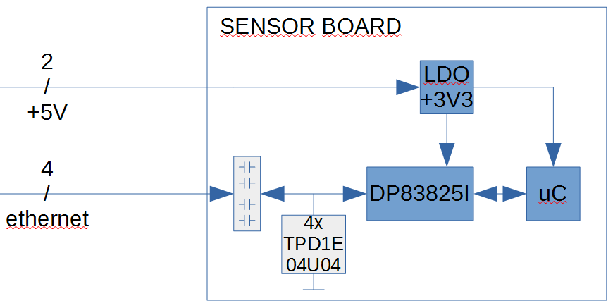
    I've drawn the block diagram of the system:

    As you can see, DP83825I are capacitive coupled on ethernet bus side (no magnetics on boards)

    Master board is always ON and running, waiting for sensor board that will be connected and disconnected many times.

    With "hot insertion" or "hot plug" I mean that sensor board can be connected to an already powered on and running master board.

    I noticed that  PHY on sensor board brokes very easily during connecting-disconnecting operations.

    Where is the problem?

  • Hi Marco,

    There could be an issue with hot insertion in this situation. Do you have an ESD diodes or ESD protection for this situation? There could be a large voltage carrying over causing overvoltage on the PHY.

    Thanks,

    Cecilia

  • Yes, I have 4x TPD1E04U04 ESD diodes on board inserted between PHY and capacitors, one from each ethernet line to ground,

    Is it enough?

    DP83825I seems very very weak on MDI interface.

    Thanks,

    Marco

  • Hi Marco,

    On our DP83825EVM we have used the TPD4E05U06 so I believe this should be ok. Our MDI ESD is rated at 5kV HBM. I will have to review this further internally as to why something like this could happen.

    Thanks,

    Cecilia

  • Hi Marco,

    When you say that the PHY breaks easily what exactly do you mean by that? Do you mean that the PHY is unable to work anymore or that you have to RESET the device to power up again? I need more details on that. 

    Also for the hot insertion is it that the sensor board is being connected to the already powered master board meaning the 5V and the ethernet port are being connected directly? Can you confirm if this is actually a POE type design or just capacitive coupling.

    Also you mention that ESDs are on the PHY side but have you also added ESD protection on the power rails? 

    Thanks,

    Cecilia

  • Hi Cecilia,

    my PHYs are definitively broken and unable to work anymore.
    I run also BIST tests and the only one that fails is at the AFE level (analog loopback active). All the other tests run OK.
    I run the same tests on a new working board and they perform OK at all levels.

    No, it's not a classical POE with transformer, just capacitive coupled ETH with +5V on separated lines.
    As I mentioned early, master board is already powered ON, with +5V always present on connector.
    I modified block diagram trying to be more clear.

    On power rails actually there is no TVS protection, but PHY is powered from +5V by a +3V3 LDO with 10uF input and output capacitors.
    As on block diagram, the same voltage supplies the microcontroller also.

    Many thanks

    Regards,

    Marco

  • Hi Marco,

    I still need more clarity on what you mean by the PHY is broken. Do you mean that you do not see CLKOUT, MDI signals or no communication thru SMI anymore? 

    Based on your comment you say that it is broken but you are still able to run BIST tests where all loopbacks but AFE is working. So does that mean that your suspicion is that the PHY is broken in the sense that analog loopback is  NOT working?

    Thanks,

    Cecilia

  • Hi Cecilia,

    I'm sorry for misunderstanding. I try to be more clear.

    PHY is broken on MDI interface only (ethernet differential pairs).
    CLKOUT is ok, RMII is ok, SMI is ok. PHY logic is running.

    It's impossible to communicate on MDI anymore. Resetting the device doesn't solve the issue.

    Putting an oscilloscope probe on MDI signals (Rx-Tx pairs) I can't see anymore the typical 100Base-TX carrier with MLT-3 coding
    Running BIST test it fails only at AFE level. All the other tests run OK.

    I suspect AFE brakes easily during hot insertion (connecting-disconnecting) operations.

    Many thanks,

    Marco

  • Hi Marco,

    Is there a reason that the master board requires to be on the whole time while the sensor board will be hot inserted to the master? Is there a reason you choose capacitive coupling for this design over magnetic coupling?

    Are there any connections through the connector besides the power and MDI lines? 

  • Hi Cecilia,

    • master board must be on all the time to have an improved user experience (it's a system specification);
    • we choose capacitive coupling for the smallest occupied area on sensor board;
    • no, there are no other connections on board.

    Many thanks,

    Marco

  • Hi Marco,

    Do you have the length of the cable you are using to connect between master and sensor board?

    Also, can you share a screen capture of what the layout of your ESD diodes look like? 

    One more confirmation to know that the PHY is fully broken, could you move the failed unit (broken AFE side) to a GOOD board and confirm that you still don't see the signals on the MDI side? I want to confirm this before we can potentially move forward with a failure analysis.

    Thanks,

    Cecilia

  • Hi Cecilia,

    the cable used was approx. 10m.

    - could you move the failed unit (broken AFE side) to a GOOD board and confirm that you still don't see the signals on the MDI side?

    Are you proposing to desolder broken PHY from sensor board and solder it to another surely working sensor board, or simply attaching broken sensor board to another working master board?

    The first option is not so simply to achieve because of reduced phy dimensions and the four square pads on corners.

    Many thanks

  • Hi Marco

    Yes I mean the first option. The reason I want to see if this is possible is to confidently confirm that the broken device does not follow the boards. If we see that it is not working properly on a surely working sensor board then we can indeed conclude that the DP83825 is broken on the MDI side and no other issues are on the board.