This thread has been locked.

If you have a related question, please click the "Ask a related question" button in the top right corner. The newly created question will be automatically linked to this question.

DP83867IR: MDIO not working & RGMII not working neither.

Part Number: DP83867IR

Hello,

We designed some custom FGPA firmware with our own Ethernet stack we tested the firmware with development boards and now we've designed a custom PCB where we are trying to implement the system. The main problem we have now is that the RGMII is not working properly. I wanted to access the chip via MDIO to try to solve it, but it's not working neither.

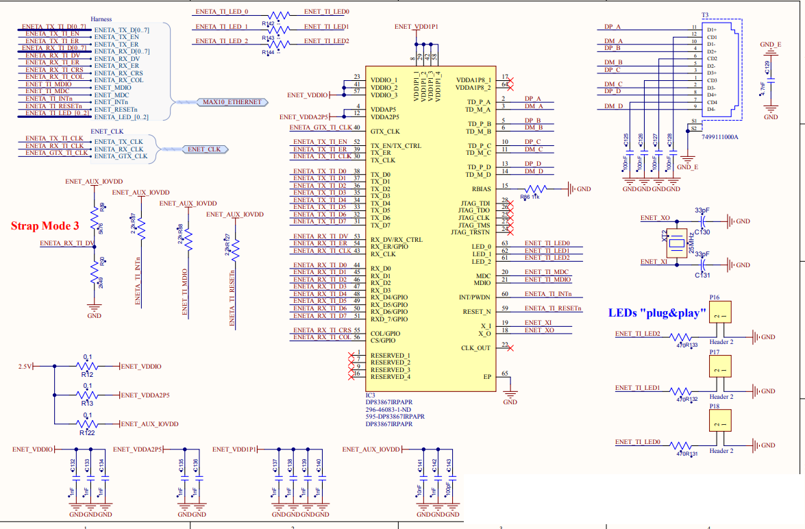
I have output signals, so the chip is doing something, anyway, I'll first want to fix the MDIO problem. This is the schematic:

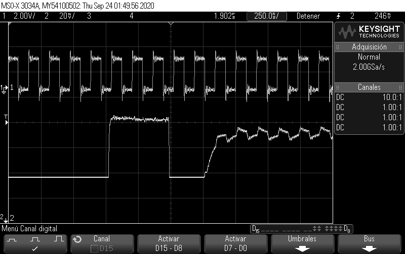
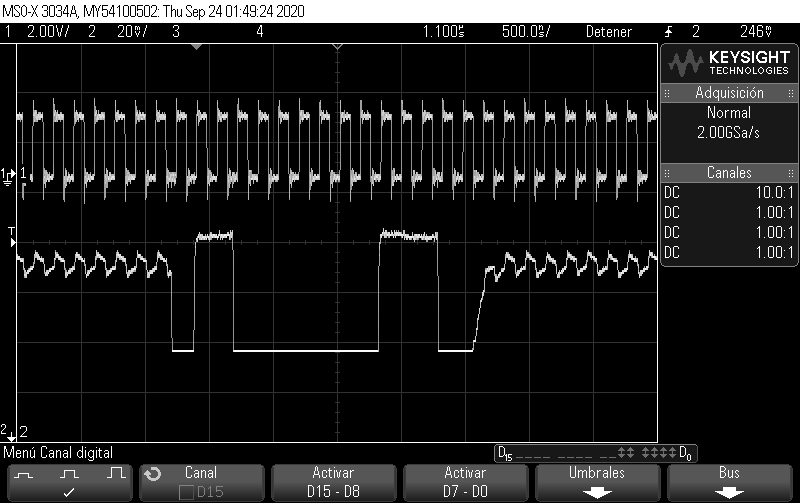
And that's what I'm seeing when looking at the MDIO:

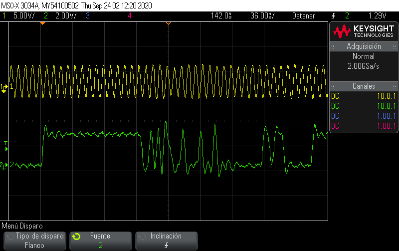
I'll also add some images of the TX RGMII not working properly.

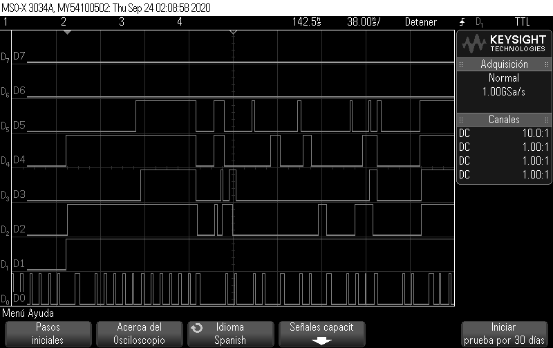
D0: Tx CLK, D1: Enable,  From there Data from 0 to 3.

Any ideas? To communicate we are using an FPGA, it has worked with other chips. 

Thanks,

GG

  • Hi GG,

    Do you have a pull up resistor to VDDIO on the MDIO pin as per our recommendation in our datasheet? I do not see it on your schematic. 

    Is there anything else connected to the MDIO pin? Would you be able to use an mcu to use as external MDC and MDIO?

    Thanks,

    Cecilia

  • Hello Cecilia,

    The pull up you're mentioning is R88, you can see it next to the "Strap Mode 3" text, it's the 3rd circuit on that row. For what I recall the pull up was only for MDIO not MDC, right?

    The MDIO is connected to the FPGA pin and it goes throgh one 0 ohm resistor and a test via, that's it.

    Using a MCU as a permanent solution would be impossible, but it might be possible to connect some MCU board externally to the pins to check if the problem might come for the FPGA, anyway I can't do that until next week, I don't have access to the uC boards until then.

    Thanks,

    GG

  • I changed the pull-up resistor from 2k2 to the IEEE value of 1k5, but it still doesn't work. At the moment using an MCU is imposible with additional work as all the uC that we have available use different pinout voltages (I'm working at 2.5V).

    I tried some changes in the FPGA firmware, checked PCB connectivities, etc...But I'm still in the same situation. I can't manage to communicate with the chip.

  • Hi GG,

    In the first two screenshots, is signal 1, MDC and signal 2 MDIO? Also just wanting to confirm that I'm reading this correctly that MDIO is at 20mV/div? What voltage is the FPGA using for its MDC and MDIO signal? 

    Also in the last image what is signal 1 yellow and signal 2 green? The quality of the clock and data does not look very clean. So i want to confirm the signal integrity of your crystal and RX_CLK. 

    Thanks,

    Cecilia