This thread has been locked.

If you have a related question, please click the "Ask a related question" button in the top right corner. The newly created question will be automatically linked to this question.

TCAN4550-Q1: About the functional modes of the TCAN4550

Part Number: TCAN4550-Q1
Other Parts Discussed in Thread: TCAN4550,

Hello,

I am currently investigating the TCAN4550 for my application, and I need some clarifications for how the device modes work (i.e. Normal, Standby, Sleep). I won't go into the Failsafe modes for now as I need a grasp on these first three modes first. In my setup, ma micro-controller is driving the TCAN4550 chip through the digital GPIO pins of the chip, notably the nINT and the nWKRQ pins to manage all interruptions. In this case, the nWKRQ has been configured as the Wake request interrupt.

I would like to understand the operational differences of going from Standby to Normal, and of going from Sleep to Normal. Here is my understanding :

  • Standby to Normal : on a Local Wake-Up (LWU) or CAN Wake-Up (WUP) event, the nWKRQ pin will be pulled low (nINT as well, as it is a logical OR of all interrupts). In this case, the host microcontroller may simply write 0b10 into the MODE_SEL bit field of the 0x0800 register through the SPI bus, and the incoming frame will then be acknowledged by the TCAN4550.
  • Sleep to Normal : a LWU or WUP event will cause the chip to automatically transition from Sleep to Standby mode. At that point, the nWKRQ pin will be pulled low (mirrored by nINT once more). In this case, the host microcontroller must fully re-configure the TCAN4550 in order to acknowledge the incoming frame.

My question then follows. If what I just explained is accurate:
How may the host microcontroller know during an interruption triggered by the nWKRQ pin if the TCAN4550 was in Standby or in Sleep mode when the LWU/WUP event occurred. I need to know how to handle the wake up as cleanly as possible, and for now it is not clear when I need to simply transition to normal through a SPI write or if I need to completely reconfigure the component.

Corollary questions:
When the device is in Standby and a WUP takes place because I am sending it CAN frames, it won't acknowledge the incoming frame right away. It usually takes the automatic re-transmission of 2-10 CAN frames (depending on transmission rate, and how the nWKRQ interrupt is handled). This is because the SPI transaction between the microcontroller and the TCAN4550 requires a read and then write of the 0x0800 register. It takes even longer if it is handled through the nINT interrupt, as it becomes necessary to read the interrupt registers to find out if it is indeed a Wake event that needs to be handled.
Is there a way to make this acknowledge slot happen faster other than increasing the speed and efficiency of the SPI communication ?

Thank you for your help.
Best regards,

Louis

  • Note: This post has been edited by Jonathan to clarify and correct some statements in the original post. The edited content is in Bold font.

    Hello Louis,

    Thank you for your interest in the TCAN4550-Q1!

    I would recommend you reference the Device State Diagram (Figure 23) in the TCAN4550-Q1 datasheet to see the details of what events cause a mode change in the device. I think there are a few things based on your description that might need some clarification or correction. I will try to address those clearly.

    The TCAN4550-Q1 both Powers up and Wakes Up into Standby Mode where it waits for configuration by the MCU. While in standby mode, the device is not capable of sending, receiving, or acknowledging any messages on the CAN bus and the MCU will need to configure all of the device registers if it has just powered up or transitioned from Sleep Mode. Only at the end of this configuration sequence should the device be set to Normal mode through the MODE_SEL bit field of the Modes of Operation and Pin Configuration Register 0x0800[7:6]. If the device has been configured and placed into Standby Mode by the MCU, it will retain the configuration settings and does not need to be reconfigured before transitioning into Normal Mode through the MODE_SEL bit field. Once the device enters Normal mode, it will start participating in activity on the CAN bus. This is why it is important to have the device configured prior to placing the device into Normal mode because an incomplete configuration could lead to CAN errors.

    The device can be placed in to Sleep Mode through the same MODE_SEL register bits while the device is in either Standby or Normal Modes.

    However, if the device is in Standby Mode, it can also automatically transition back into Sleep Mode if the Sleep Wake Error timer (SWE_DIS) times out. Upon Power Up or a Wake Up event where the device exits Sleep Mode, a 4 minute timer starts and this timer must be disabled, or the device must be configured and placed into Normal Mode before the timer expires otherwise the device transitions back into Sleep Mode. This is a failsafe feature to prevent the device from exiting Sleep Mode due to noise or some other factor when it was unintended.

    So to summarize, the device is either:

    1.)    Powered Down (Vsup is not supplied to the device)

    2.)    In Sleep Mode (almost completely powered down except for the Wake Up Detection circuitry)

    3.)    In Standby Mode (fully powered but not fully configured and will not participate in activity on the CAN Bus)

    4.)    In Normal Mode (fully powered, fully configured, and actively participates on the CAN Bus)

    When the device is in Sleep mode and a Wake Up event occurs either through a LWU on the WAKE pin, or a WUP on the CAN bus, the TCAN4550-Q1 will automatically transition to Standby Mode, the Inhibit (INH) pin will be driven high to the VSUP voltage which is typically connected to the Enable Pin of an LDO or DC-DC converter that supplies the VIO voltage rail to the MCU and TCAN4550-Q1. When the VIO rail is active, the MCU will wake up and configures the TCAN4550-Q1 as part of the initialization process. In this way the entire board can be placed to sleep except the Wake Up detection circuitry inside the TCAN4550-Q1.

    However, not all systems want to use the INH pin to wake up the power to the board and therefore the Wake Request Pin (nWKRQ) can also be used to provide an indication to the MCU that the TCAN4550-Q1 has detected a Wake Event and transitioned into Standby mode. In this case the nWRQ pin will transition Low and either be latched low as long as the device is not in Sleep Mode (which mimics the INH functionality) or it will be latched low until the Wake Up flag is cleared in the Interrupt Register.

    If the device has entered Sleep Mode through an event not controlled by the MCU changing the MODE_SEL bit field, the Sleep Mode Status (SMS) bit of the Interrupts register (0x0820[23]) has been set. This can be used as an indication that the device was in in Sleep Mode during the Wake Event. You can use this bit as one indication that the device will need to be re-configured because all of the configuration register values will have been lost while in Sleep Mode.

    When the device is in Standby Mode the INH pin is already high and can’t be used as an indication a Wake Up event has occurred and the device will only give one Wake Interrupt (either LWU or CANINT). This can be seen through the nINT pin if enabled, or through the nWKRQ pin if is configured as a Wake Request Interrupt in register 0x0800[8]. However in Standby Mode, the transmitter does not send data nor will the receiver accept data and the device will not send an ACK pulse to any message until it has been placed into Normal Mode by the MCU setting the MODE_SEL bit field accordingly.

    I hope this is a clear overview of the device modes and what happens during the transitions.

    To address your corollary questions, I want to make sure we are using the “acknowledge” terminology properly. The CAN standard uses the term “acknowledge” as a pulse that will be placed on the CAN bus immediately following the reception of an error free message by an active receiving node. Since the TCAN4550-Q1 is not an “active” node until it has been fully configured and placed in Normal Mode, it will never “acknowledge” a WUP on the CAN bus. If you are repeatedly sending messages on the bus to be used as a wake up pattern, the TCAN4550-Q1 will have to complete this configuration process and be in Normal Mode before it can participate in CAN bus activity and “acknowledge” any message on the bus.

    Wake Up Patterns are not usually expected to receive an acknowledge due to the fact they are telling a node to Wake Up from a Sleep State. This leads me to think you are using the term “acknowledge” to refer to a “response” from the TCAN455-Q1 as a form of “acknowledgement” or “verification” that the device is awake and functioning in Normal Mode. This will notably take a little time because the device will require the MCU change the MODE_SEL bit field if it is currently configured and in Standby Mode, and if it is in Sleep Mode it will require a complete re-configuration. But once the device is configured and in normal mode, the device will automatically place the “acknowledge” pulse on the CAN bus for any message that it receives error free. This is a function of hardware and requires no SPI activity.

    However if you are expecting the TCAN4550-Q1 to send a message as an “acknowledgement” this will not happen automatically and will require communication between the MCU and TCAN4550-Q1 on the SPI bus. Optimizing the MCU firmware loop with as little overhead as possible and using the SPI as efficiency as possible through the maximum possible data rate and using Burst Reads and Writes are critical to achieving the best turnaround time between receiving a message and sending a response message.

    The final point I will address in this thread is the time difference between using the nWKRQ pin as compared with the nINT pin as an indication to the MCU that the TCAN4550-Q1 in Sleep Mode has seen a Wake Event and entered the Standby Mode. The nWKRQ pin will always be faster because it is active while the device is in Sleep Mode and indicates the event immediately following the wake up event. Once this occurs the TCAN4550-Q1 will start to power on the digital circuitry, start the crystal oscillator, and eventually enter Standby Mode. Only once the device has entered Standby mode will the nINT pin be driven Low to indicate any interrupt flags that have been set which include a few flags set as a result of the Wake Up event. This timing is shown in the Sleep to Standby Timing (Figure 16) of the datasheet.

    By default the nWKRQ pin is configured to mirror the INH pin behavior and stay latched low while the device is not in Sleep Mode. However if it is configured as an interrupt pin, it will represent the Logical OR of the CANINT, LWU, and WKERR interrupt flags and it will stay latched low until the interrupt flag is cleared. If the CANINT, LWU, and WKERR flags are not masked, they will also cause the nINT pin to pull low until they are cleared.

    I hope I have addressed all your questions, but please let me know if you have any follow up questions.

    Regards,

    Jonathan

  • Hello Jonathan,

    First of all, thank you for your thorough reply. I will take the opportunity here to make some clarifications, and share some of my observations with you.

    Your recap of the overall functional modes of the TCAN4550 is useful. You are confirming most of what I understood, with the exception of a few things that I have observed differently. Before I go further, I just want to make it clear that I understand that the device needs to be configured after it reaches Standby mode following a start up. However, for power budget reasons, I need to transition the transceiver from Normal to Standby from time to time. Another thing I need to make clear, when I talk about acknowledgement, I do mean ACKs in the transfer layer of the CAN protocol. Namely, the dominant bit that a receiving CAN transceiver must pull during an ACK slot, and I am not talking about an acknowledgement message which should be implemented in the application layer above the CAN protocol.

    My first observation by experimenting with the TCAN4550 contradicts what you say here:

    Wake Up Events are only valid when the device is in Sleep Mode. [...] If the device is in Standby Mode, any activity on the CAN bus that meets the Wake Up Pattern or WUP will be ignored because the device is not capable of sending, receiving, or acknowledging activity on the bus.

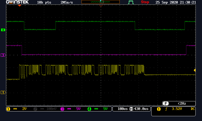
    I believe I may have used the wrong terminology when I say "wake" from Standby to Normal, it probably rather should have been "service". However, I can say that the WUP absolutely does have an effect on the TCAN4550 in Standby mode. The nWKRQ interruption (talking about the interrupt, not the pin!) is routed through the nINT interrupt line: when a new CAN frame with the pattern was incoming, I could observe that this interruption triggered properly, and I could use it to make the microcontroller service the transceiver by transitioning it from Standby to Normal through a SPI write. Note once more that this is after startup, configuration in Standby mode, and nominal use of the Normal mode for a few CAN transactions; I had put the device from Normal to Standby to test how it can be used in my application. I would also like to note that the nWKRQ pin (this time I really mean the pin, not the interrupt) also reflects what I have mentioned. Please refer to the oscilloscope screenshot I have attached below:

    The CANH line is in yellow, and the nWKRQ pin of the TCAN4550 is in purple. The green signal is a GPIO signal coming from my microcontroller used for debugging purposes and may be ignored. This figure shows what happens when another actor on the CAN bus starts broadcasting a frame with automatic re-transmission on failed transmissions. You will see that the nWKRQ pin is pulled low during the broadcast of the first frame. After transitioning the TCAN4550 from Standby to Normal through an SPI write, the transceiver is finally in Normal mode and capable of acknowledging the fifth frame (i.e. fourth re-transmission). Once this is done, the interrupt register is written back to in order to clear the interrupts, and you may see that the nWKRQ is released back to high after a time.

    I have an issue with this:

    In Standby Mode (fully powered but not fully configured and will not participate in activity on the CAN Bus)

    So if the device is in Standby mode, does that automatically mean it should be reconfigured anyway ? The use of a Standby mode is rather limited in this case if it cannot be used to actually stand by while waiting in a lower power state for the next series of communications. If it must be reconfigured every time, the latency in the replies will become problematic, as I have measured about 50 ms of configuration time using the example code provided by TI.

    And finally:

    If the device has entered Sleep Mode, the Sleep Mode Status (SMS) bit of the Interrupts register (0x0820[23]) has been set. This can be used as an indication that the device was in in Sleep Mode during the Wake Event.

    I have just verified this and this is not entirely correct. The SMS bit of the interrupts register will only be set to 1 if the device has transitioned to Sleep due to a WKERR, UVIO timeout, or UVIO+TSD fault (as per the datasheet). However the SMS flag will be set to zero if the host microcontroller has willingly transitioned the TCAN4550 into Sleep mode from Normal/Standby. This is useful to know if the device needs to be reconfigured if an error has occurred (for instance, if the microcontroller has failed to configure and transition it to Normal mode within 4 minutes of Power On, or after a Wake from Sleep if the SWE_DIS bit in register 0x800 is set to 0). In this case, I would still need to keep track of the TCAN4550's mode on the microcontroller side to differentiate when the device was set to Sleep by the microcontroller and when the transceiver was in Standby.

    Once more, I would like to thank you for the clarifications. I hope that a better understanding of the use of the TCAN4550's functional modes can be had from our exchanges, and I am looking forward to reading your take on what I have shared here.

    Best regards,

    Louis

  • Hello Louis,

    Thank you for the clarifications and observations. I will admit I was a little bit confused by a couple of things in your original post, but I now have a clear understanding of what you are asking and trying to accomplish. I will also admit that I completely misspoke on the Wake Up behavior in Standby Mode. You are correct and I am at a loss of words why I would state that Wake Up functionality is not available in Standby Mode other than I think I was thinking in terms of waking up from a true Sleep Mode and I just had a mental lapse on the Standby Mode. I apologize for the confusion, but I have edited my original post to correct and clarify the information in the post.

    I addressed your latest question in the edits, but no, the device does not always need to be re-configured when in Standby Mode before transitioning into Normal Mode. If the device was placed into Standby Mode by the MCU through the MODE_SEL bit field, then it will retain all the configuration settings and will only need to be placed back into Normal Mode through the MODE_SEL bit field after a Wake Up event is detected.

    Unfortunately the SPI bus is both a feature and a limitation depending on your perspective. It allows the device to be used in any number of systems with any MCU that has a SPI bus. In that regard it is an enhanced feature. However, it is a limiting factor on the total throughput and response time for CAN related activity such as Wake Up Events due to the extra time required to pass the information between the device and the MCU through the SPI bus. My only recommendations on reducing this is to use the fastest SPI rate possible, and to make the MCU firmware structure as optimized as possible so that it can detect and respond to an interrupt from the device as quickly as possible. Outside of that, there is not much that can be done.

    It sounds like you have a good understanding for how this device works and transitions between the modes, but if you have any additional questions please let me know.

    Best Regards,

    Jonathan

  • Hello Jonathan,

    Thank you for your clarifications ! No issue taken with the initial quid pro quo, I made the mistake of using the word "wake" a too liberally when discussing the transition between modes.

    Fortunately, discussing these aspects of the device have cleared things up, and I know now that I need to somewhat keep track of what the MCU has requested to the TCAN4550 so that I am able to differentiate between a transition from Sleep or Standby. This must be done while checking the SMS flag on every nWKRQ interrupt to make sure the device hasn't set itself to Sleep mode without the MCU knowing about it.

    This has resolved my questions. Should I have any further questions, is there a way I could reach you directly in the future ? (e.g. mail)

    Best regards,

    Louis

  • Hello Louis,

    Great! I am glad I was able to help.  Good luck with your development and I will send you an email to the address associated with your E2E account that you can use to contact me directly if you have questions in the future, or you can always post again in this forum.

    Regards,

    Jonathan