This thread has been locked.

If you have a related question, please click the "Ask a related question" button in the top right corner. The newly created question will be automatically linked to this question.

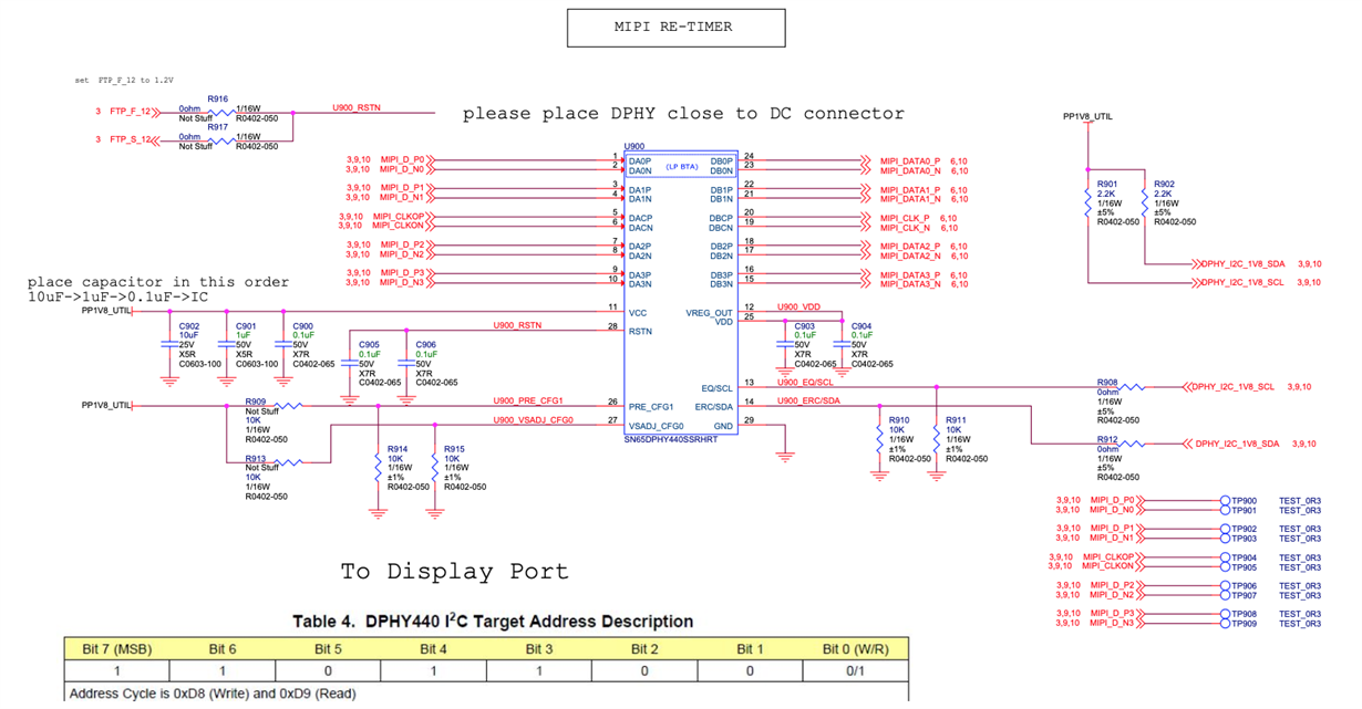
SN65DPHY440SS: SN65DPHY440SS entered ULPS mode without host sending 00011110, host needs to wait long time to send 05 11 (sleep out) to display DIC

Part Number: SN65DPHY440SS

Hi Ti Team,

I got an abnormal behavior using SN65DPHY440SS since last year. My display DIC failed to get sleep out command at 2nd time display on (i.e. display on, display off, then display on again). It is proved that Sleep out (05 11) was not sent at the output of  SN65DPHY440SS. Could you help with some advice regarding the re-timer and its ULPS mode?

Setup: FPGA MIPI host -> re-timer -> Display DIC

HW Schematic: SN65DPHY440SS has reset constantly pulled up to power supply. I am expecting it is always active.

MIPI command: we have probed the input of re-timer, both display on & off does not send 00011110 command (trigger ULPS mode)

2nd display on shows not Sleep Out waveform at the output of SN65DPHY440SS.

Hypothesis: SN65DPHY440SS entered the ULPS mode.

Workaround: add delay 40ms to activate the re-timer, then send 05 11. It was proved 100% display on every time.

I could not find more info regarding ULPS on the data sheet.

Thanks,

Nu

  • Nu

    The DPHY440 has an internal 300k pullup, you should have an external pulldown cap to create the RC time constant delay. The recommended cap is 0.22uF.

    Thanks

    David

  • The reset pin already has the cap.

    My problem is not about not able to use the re-timer. I am able to 100% display on my panel for the 1st time, but I can not light up display for a 2nd time. SN65DPHY440SS seems to be in ULPS mode because I failed to get 05 11 at the output for the 2nd time light-up. 

    Since the reset is always high and MIPO host does not send command SN65DPHY440SS to ULPS, I am curious any other reason the we failed to light up display at the 2nd display on.

    Thanks,

  • Nu

    Can you clarify your workaround, add delay 40ms to activate the re-timer, how do you do that?

    If the DPHY440 is in the ULPS state, do you issue a ULPS Exit command to exit the ULPS state?

    Thanks

    David

  • Thanks David,

    If the DPHY440 is in the ULPS state, do you issue a ULPS Exit command to exit the ULPS state?

    >> actually, I have have no idea what happened to DPHY440, and why it does not output 05 11 for my 2nd display on 05 11 command. ULPS is my hypothesis. I appreciate your guidance check what happened to the re-timer.

    If available, I can setup cc and share my screen for discussion.

    Can you clarify your workaround, add delay 40ms to activate the re-timer, how do you do that?

    >> delay between D0P/D0N high to  1st command 05 11

    40us : 1st screenshot

    40ms: 2nd screen shot.

    Thanks,

  • Nu

    Thanks for the clarification on the workaround.

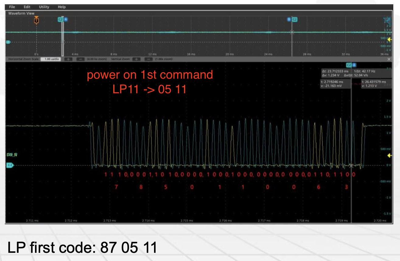
    If you look at the DPHY440 functional modes diagram, you can see a LP11 is needed for the DPHY440 to exit from the ULPS state and into the LP state. Your scope picture shows the D0P/N are driving the '11' condition on the bus before sending the MIPI command of 05 11. The DPHY440 data sheet does not state the required LP11 timing. I am checking with the design team on this timing requirement and will reply back to you as soon as I have this information. 

    Thanks

    David

  • Hi David,

    "If you look at the DPHY440 functional modes diagram, you can see a LP11 is needed for the DPHY440 to exit from the ULPS state and into the LP state."

    This is my workaround and also where my confusion comes from. I do not know why DPHY440 has long response time after LP11. My guess is that it goes into ULPS mode. Would you mind help check with design team or application team when DPHY440 would have long response? If that is related ULPS, without sending ULPS command or toggle reset low, is there any other trigger make it sleep?

    Our top confusion is DPHY440 has long response time and what made it "sleep".

    "The DPHY440 data sheet does not state the required LP11 timing."

    Regarding LP11 timing, I also failed to find the info from data sheet. But I got something from the MIPI standard. 

    Thanks,

  • Nu

    I am checking with the design team on the DPHY440 long response time as it seems to me the 40ms seems too long. 

    Thanks

    David

  • Nu

    The design team feedback is that the transition time from the ULPS state to the LP state is 145ns + 10UI.

    Can you please take a zoomed-in scope plot right before the 05 11 command is being issued? Please include both the D0P/N and CLKP/N as we want to see how the DPHY440 is being transitioned from each state on these lanes.

    Thanks

    David

  • Can you please take a zoomed-in scope plot right before the 05 11 command is being issued? 

    Screenshot is showing the 1st command for our display on sequence. LP11 -> 05 11. The waveform is captured at the input of the DPHY440

    Since sleep out is the 1st command under LP mode, do we really need CLK? The Clock was not captured and we may need to re-capture it.

  • Nu

    Yes, can you please capture the clock waveform right before the LP command of 05 11?

    Thanks

    David

  • Hi David,

    Currently I may not have bandwidth re-capture the clock in short-term, so there maybe delay in the reply. Do you have any expectation for the waveform? and can we prioritize finding why DPHY440 entering the ULPS mode?

    Thanks,

  • Nu

    The ULPS entry pattern are different for clock and data lanes.

    On the clock, starting from the Stop state, the transmit side drives TX-ULPS-Rqst State (LP-10) and then drive TX-ULPS State (LP-00). After this, the Clock Lane enters into the ULPS state. 

    On the data lanes, If the Ultra-Low Power State Entry Command (00011110) is sent after an Escape mode Entry command, the Lane will enter the ULPS state.

    Thanks

    David