This thread has been locked.

If you have a related question, please click the "Ask a related question" button in the top right corner. The newly created question will be automatically linked to this question.

TUSB321: TUSB321 can't detect the current mode from upstream side

Part Number: TUSB321

Hi Team,

I would like to get your assistance regarding our customer issue with their design using TUSB321.

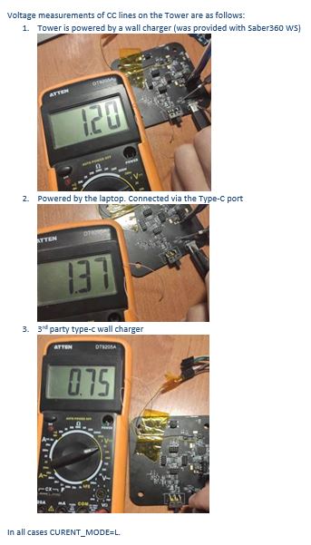
They use TUSB321 in UFP mode, but it can't detect the current mode from the upstream side, and always report the lowest current only whatever the power source is.

Here's part of the schematic. Please let me know your inputs and questions.
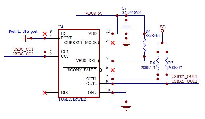


Thanks.

Jonathan

  • Hi Jotnathan,

    Has the customer tried powering TUSB321 externally and seeing if the OUT pins reflect the correct state when a DFP is connected?

  • Hello Malik,

    I just got the response from my customer after sharing the information you shared.

    According to the customer, their field engineer report they use a 3A wall adapter, type C-C cable connected to UFP device with TUSB321 on it, the CC lines measured voltage are 0V/1.3V on same side of TUSB321 located, and the OUT1=H, OUT2=L, which means 0.9A/0.5A current rating detected.
    Another Question: if the wall adapter side just have a simple 10k pull up to 5V, will TUSB321 driving CC lines to different voltage at different time to detect the current rating ? or the CC lines should be stay on a voltage in this case ?

    Please let me know your comment.

    Regards,

    Jonathan

  • Hi Jonathan,

    When TUSB321 is configured as a UFP only Rd is presented on the CC pin. The CC voltage is only monitored to update the OUT pins. The CC voltage should be consistent in the case when Rp and Rd are connected. I believe that TUSB321 is connecting in dead battery mode and OUT pins are reflecting default current advertisement. Can customer trying testing with external power supply to TUSB321?

  • Hello Malik,

    Thank for this information.

    Upon discussing with the customer, they informed us that they don't have any battery in system, the power source (up stream side via C-C cable) is power adapters or computer type C port.

    By the way, here's the image for their measurement.


    Looking forward to your comment.

    Regards,

    Jonathan

  • Hello,

       You can see we have different voltages (from different power sources) shows on CC line to the TUSB321 device, but we haven't see any difference output from TUSB321.

       We are using TUSB321 to detect the power source's capability and decide to use how much of power in our system loading controlled by firmware.

       We currently stuck here for product development, and face to change method to do the job.

       Please help.

    -Sherman Wei

  • Our power adapter supplier share their schematics to us, and it support PPS,PD2.0/PD3.0,QC3.0/QC2.0,FCP,SCP, AFC, Apple 2.4A,BC1.2, and we also noticed the CC line changes, the problem is the TUSB321 can't do his job to report the capability of power, always say it is 0.9A/5V power source.

  • Hi,

    Since TUSB321 is powered by Vbus, all connections will be made under dead battery mode. In this mode TUSB321 will no be able to report the advertised current mode. Are the results reported above tested with TUSB321 power from external supply or Vbus (Vcc > 0v)?  

  • Yes, it is powered by VBUS, anyway we can move it away from the "dead battery" mode ?

    the VDD need be powered by a voltage of 4.5V~5.5V, what should we connected to avoid the "dead battery" mode?

    Please advise in 2 days, as we are final step to decide if we keep this part in design.

    Thanks,

    -Sherman

  • the datasheet even not mentioned the "dead battery" mode

  • other post says it will enter into "dead battery" mode when VDD's power is removed, we have 5V on it all the time, how we will also enter into the "dead battery" mode?

  • Hi,

    In your schematic you have TUSB321 powered by Vbus. Before a connection Vdd will be 0V until connected DFP see Rd (from dead battery mode) and enables Vbus. Are you saying that Vdd is externally powered in your testing or is Vdd powered from a Vbus that is always enabled during testing? 

    Dead battery mode is described in TUSB321A datasheet, TUSB321 also includes this feature. 

  • That is correct, dead batter mode is entered when VDD is 0V. If a constant 5V still results in the same behavior then it is possible the device is being back driven by the 3.3V rail pullup on OUT1/OUT2. Please make sure 3.3V goes high after 5V Vdd is stable. 

  • we are using TUSB321, not TUSB321AI, should we change and will it help to us ?

  • I do recommend using TUSB321AI instead of TUSB321 for updated internal state machine and lower current consumption. You should still ensure that 3.3V becomes stable after Vdd so that TUSB321AI is not back powered when Vdd is low. 

  • I did another test with VDD (5V) applied before, same time and after the type C cable connected, all of them report same lowest current, whatever the host side is.

  • Hi Sherman,

    Was VDD (5V) stable before 3.3V rail where OUT1 and OUT2 are pulled up during the initial power-up? 

  • so we need the 5V much earlier then pull up 3.3V ?

    how much of the time ?

  • I connected the pull up 3.3V a minutes after 5V, the result is still not changed

  • This is not expected. Powering 3.3V before 5V can cause the internal to enter a bad state. 5V should be stable for at least 2 ms before 3V is stable. You see this issue on two platforms correct? Have you tried replacing the parts with new devices on the no good platform? Also from your testing, do you have a waveform with CC1, VDD5, 3.3V OUT1 (assuming only 1.5A advertisement should be detected).

    Is it possible some other device is holding down OUT2? No sure since there is only a partial schematic. 

  • the OUT1/2 are connected to MCU GPIO as input, nothing else connected to them.

    I think new device you mentioned is TUSB321AI, we don't have it in hand, not try it yet.

    our firm team test many platform, I did a couple of them also. 

    we have no time to try it, but I will keep replace it with TUSB321AI in next build in next week and see if it report good result, otherwise I will remove it from design.

    -Sherman

  • Hi Sherman,

    Please let me know the results and remember to power-up the device with an external 5V first then 3.3V. After power-up connect charger (or Type-C device).  OUT1/2 pins should reflect the current advertisement as reflected by the measured vRd. Also I would double check that MCU GPIO does not control OUT 1/2 nets erroneously.