This thread has been locked.

If you have a related question, please click the "Ask a related question" button in the top right corner. The newly created question will be automatically linked to this question.

DP83826I: Differential pair trace length from PHY to magnetics of < 25mm is OK?

Part Number: DP83826I

Hi. 

We will be using DP83826I with a discrete magnetics (XFMRS P/N: XFATM9B). Datasheet is attached. In the following layout considerations from PULSE Transformers and another write up in Signal Integrity magazine, it was recommended to make the differential pair trace length from PHY to the magnetics' input at least 25mm (~1-inch) to reduce EMI. I haven't seen this layout recommendations in any of the TI's, Microchip's, or Marvell Semiconductor's application notes. Is this distance required for Ethernet PHYs? Do you have any recommendation for the total trace length should be from the magnetics to the Ethernet PHY for best performance and EMC? 

https://www.networking.pulseelectronics.com/hubfs/connectors/Pulse_Layout%20Considerations%20v7.pdf?hsLang=en-us

https://www.signalintegrityjournal.com/articles/1808-ethernet-connectors-and-routing-above-ground-planes

Thanks,

Fazlul

Pepperl+Fuchs, Inc. (Minneapolis)

fkarim@us.pepperl-fuchs.com

  • Hi Fazlul,

    There is no minimum required distance between the PHY and magnetic. The 25mm spacing can be used however TI does not view it as a requirement or guideline. Keeping the trace length small improves the common mode noise and EMC performance, and 25mm would be considered well within the recommended length. 

    Regards,
    Justin 

  • Hi Justin, 

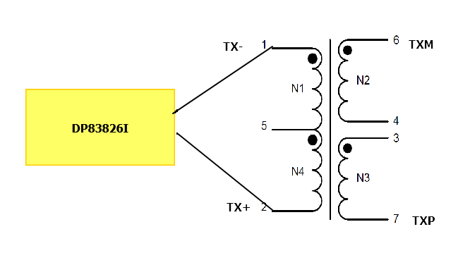
    I have an additional question regarding the polarity of the LAN transformer. We are specifying XFMRS LAN Transformer P/N: XF4P4532-381-7P for the isolation transformer implementation. it's schematics is shown below. Currently, the TX+ and TX- from the PHY are connected to Pin 1 and 2 on the transformer, respectively. With these connections and because of how the transformer's pins are on the package, the signal traces criss cross and the only way to get around is that by adding two vias per trace (e.g. Transformer, TVS, and Ethernet PHYs are all on the same layer). We would prefer it to not add any vias to the differential pair traces from the TVS to the Ethernet PHY differential pair pins. (Although this is still an option). 

    Couple of questions: 

    1. What would be the impact to PHY and Ethernet's operation if we swapped TX+ and TX- pins on the transformer? Instead, Tx+ connects to Pin 2 and Tx- connects to Pin 1. We would flip the connection on the secondary side as well (Pins 6 and 7) to match the primary side to connect to the connector. Please see the attached diagram. 

    In addition to the Tx+ and Tx- swapping on the transformer pins, we would need to do this swap on the transformer pins for the Rx+ and Rx- pins. 

    Would DP83826I be able to support ethernet signaling and operation seamlessly in this proposed configuration? 

    At the moment, I didn't plan on swapping the +/- pins on the DP83826I's pins to use its auto-polarity correction functions. I was thinking that it might add delay in DP83826I to establish link with its link partner. Correct me if I am wrong about it. 

    Looking forward to your recommendation for the above question. 

    Thanks,
    Fazlul

    fkarim@us.pepperl-fuchs.com

  • Link to the transformer's datasheet: 

    xfmrs.com/.../XF4P4532L-381-7P.pdf

  • Hi Fazlul,

    The polarity of the TX and RX MDI channels can be swapped on the DP83826. The DP83826 is immune to polarity issues in 100Base-TX mode because of the MLT-3 signaling. In 10Base-T mode, both channels must have the same polarity, however it can be inverted or the default. There is no programming or configuration needed to account for the polarity of the pins, this is detected automatically by the PHY. 

    Regards,
    Justin