This thread has been locked.

If you have a related question, please click the "Ask a related question" button in the top right corner. The newly created question will be automatically linked to this question.

TUSB4020BI: Start-up issue

Part Number: TUSB4020BI

We are currently having issues with the TUSB4020BI in our custom design. The device doesn't show up under the Device Manager in Windows, so it probably doesn't start.

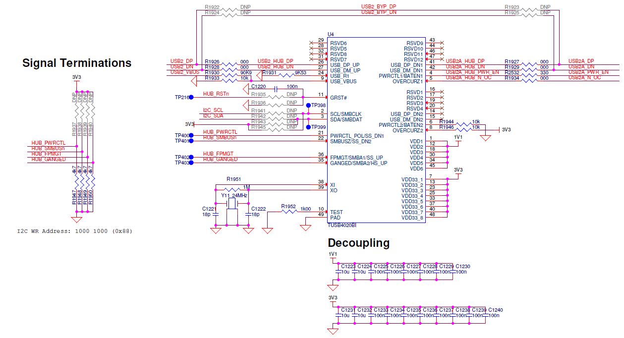
This is our schematic:

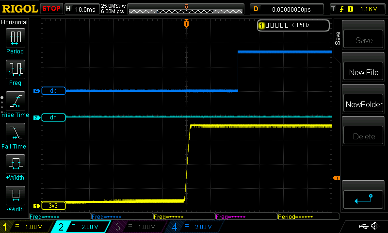
These are the waveforms of the different power rails (and the USB_VBUS signal) during start-up:

Please note that we have already tried the following modifications, but they didn't help and the hub is still missing from the Device Manager:

  • Increase the value of the C1220 to 1 uF (the oscilloscope plot above shows the GRSTn signal with this modification)
  • Remove R1948 (SMBUSZ, pin 22 external pull-down resistor)

We also tried to connect the IC to the I2C bus to be able to manually set the cfgActive bit. However, the device corrupts the otherwise normally working bus after connecting. It keeps the SCL and SDA lines at around 1,6 V.

The oscillator is running (we can measure the 24 MHz clock signal) and the IC keeps the PWRCTL1 signal low as well.
Please note that as you can see we have a bypass option for this IC and if we use it then the USB port is working with no problems (so no P/N swap or anything like that).
We have two devices on the board with the same connections and both of them behaves the same.

Thanks for any help in advance.

  • Hi Peter,

    During test we will want to keep SMBUSz pin high by removing external pull down. I2C mode does not require cfgactive bit to be set for normal operation. As a sanity check we should ensure that the thermal pad has ample solder and consider reflowing the part to ensure there are no issue in the soldering. Can you also try to measure DP and DM at power-up? I would like to investigate if USB 2 enumeration is starting correctly? 

  • Dear Malik,

    Thanks for your quick reply.

    As I wrote we have two same ICs on the board and both of them behaves the same, so I think a soldering issue is unlikely. The soldering of the visible pins looks OK.

    Here you can see the waveforms of the VDD33, USB_DP and USB_DM signals during start-up:

  • Hi Peter,

    Really sorry for the late reply? Are you still experiencing issues here? I was hoping to see 3.3V and 1.1V rail in same waveform to ensure that the power-up requirement mentioned in the datasheet.

  • Dear Malik,

    Unfortunately, we are still struggling with this issue.
    We now powered up a new board and the device behaves the same. This is the third IC we tested, so I believe that the soldering should be OK.

    Here is a now scope plot with the 1V1, 3V3, DP and DN signals on the new board:

    Do you see any problems with this power sequence / timing?
    As I wrote in the first post we only have a capacitor on the GRSTn pin (only 100 nF on this new board, but we have 1 uF on the first board).

  • Hi Peter,

    I would recommend using a 1 uF on GRST as that the voltage on the reset pin should not go high for 3 ms. Using a 1 uF ensure this is done. 

    I do not see USB 2 enumeration start in the waveform provided. Do you see any activity on the upstream USB 2 link to the USB Host (PC) or does DP stay at 3.3V when connected?

    Is USB_Vbus above 450 mV, as measured at the TUSB4020BI pin? We should also ensure that the crystal is starting up and operating appropriately. 

  • Dear Malik,

    We measure 524 mV at pin 9 of the IC and the 24 MHz oscillator is up and running as you can see on the plot below (please ignore the crosstalk due to the lazy probing):

    We see no activity on the D signals. DP stays high permanently.
    We also replaced one of the ICs now, but it didn't solve the problem.

  • HI Peter,

    Can you pull SMBUSz up to 3.3V?

  • Dear Malik,

    Thank you very much for your help. We finally figured out the source of our problem.

    We used the MP5087 load switch as the current limited power switch for the VBUS line because of the output current monitoring feature. It is not a dedicated USB power switch, so it has a PGOOD signal instead of a nFAULT and the PGOOD is false until VIN-VOUT < 200 mV. It means that the hub IC detect an overcurrent event right at the start-up and probably doesn't even try to enable the power switch.
    The TUSB4020BI started working once we removed the series 0 Ohm resistor on the OVERCURZ1 line.

    Best regards,
    Peter