This thread has been locked.

If you have a related question, please click the "Ask a related question" button in the top right corner. The newly created question will be automatically linked to this question.

TUSB4041I: Device not recognized by some PCs, unless connected via another hub

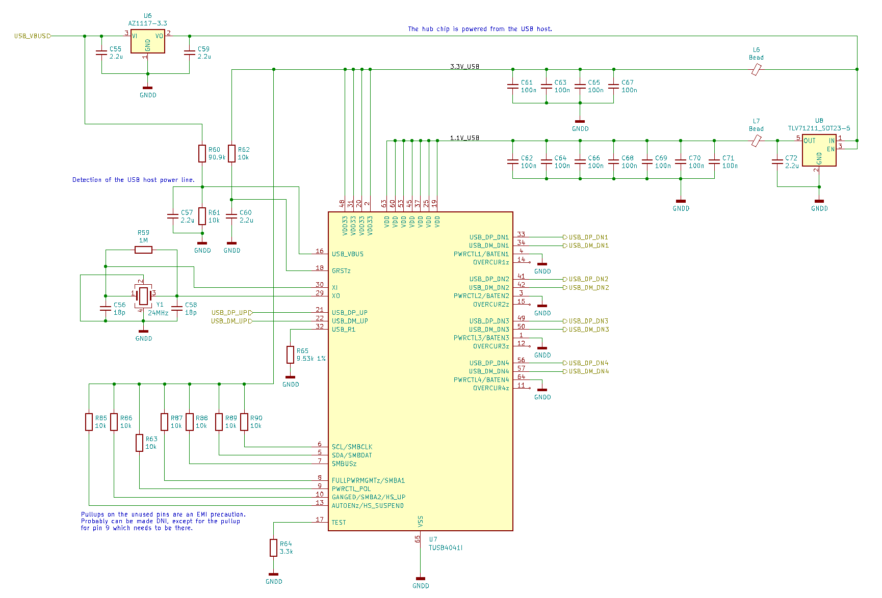
Part Number: TUSB4041I

Hello everyone,

I have a product with the TUSB4041I chip and some problems appeared recently. I will try to describe the symptoms in a compact way.

- The product was designed and built within the last year, about 20 units. Every unit works in the beginning.

- After a couple months of operation we have 4 units which stopped being recognized by some USB hosts. Once a unit stops working with a particular host, we have not seen it starting to work again.

- If a bad unit is connected via an external USB 2.0 hub (host-powered) it works just fine even with the host with which it does not work directly.

- We tried different cables.

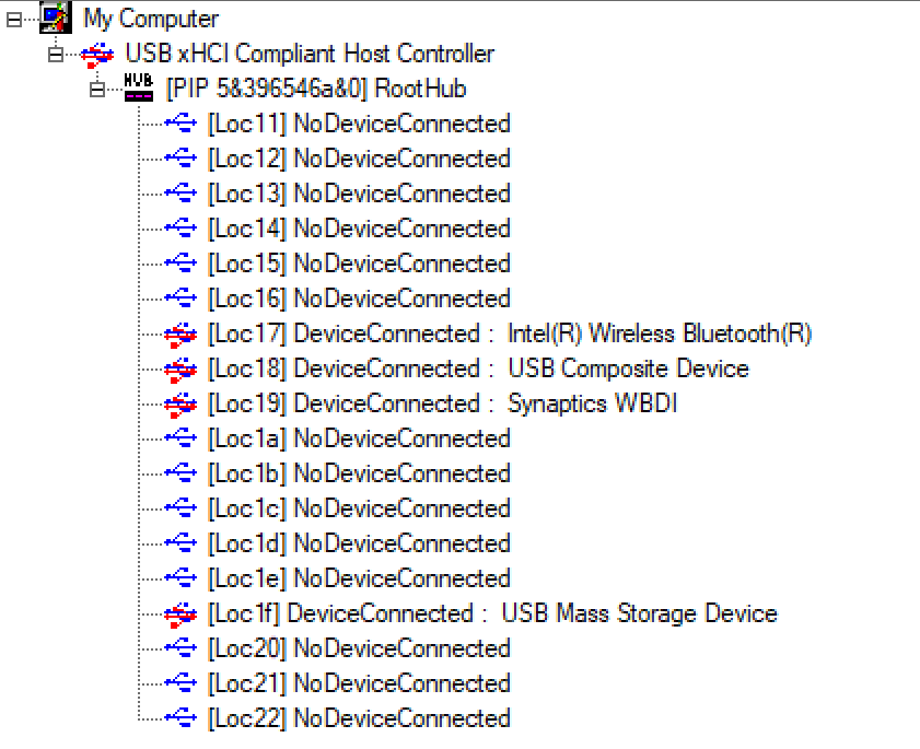
We always use computers with Ubuntu and we look at dmesg reports. If we have a unit that stopped working (all of them initially work) then the dmesg stays completely quiet after the device is connected, just like if the data lines of the USB were not connected.

The reset pin is connected to an RC circuit with time constant of about 20ms. Manually pulling down the reset pin after the device was not recognized does not help. Also power cycling without disconnecting the USB lines does not help.

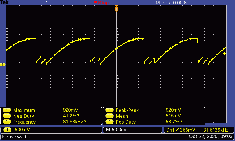
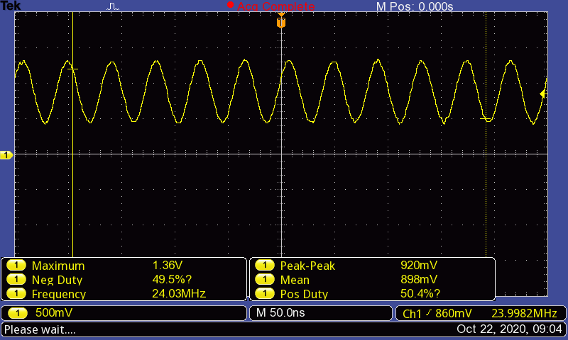
After some troubleshooting I noticed that the clock oscillator behaves strange when the system is not recognized, so I tried to tackle it there. One of the attached scope screenshots shows the strange behavior on the clock, and the other screenshot shows a nicely operating clock when the same device is connected to the same host via a USB hub. The signal is measured on one of the pins of the crystal. Note the different time scales.

The crystal used is ABM3B-24.000MHZ-10-1-U-T. I tried the following steps to see if I can make it work:

- Remove the 18p caps

- Put the caps back, remove the 1M resistor

- Put the 1M back, add a 1k resistor in series with the XO pin

After each of these steps the device was working just fine via an external hub, but did not work without (i.e. the steps taken had no effect at all, also did not make it worse).

Later I read that other people had issues with the TUSB4041 being stuck in suspended mode, and that in that mode the clock might be shut down. Is this what is happening? Can the clock look so weird when shut down?

I also read that the soldering of the heat pad of the chip is somehow critical. We have a PCB footprint which is created according to the datasheet, but we don't know what thickness stencil our assembly house is using. We also have no easy access to an x-ray. Is the solder issue purely thermal? I cannot see how the solder quality on the heat pad can affect the signal integrity as long as there is a reasonable amount of solder and a solid connection. In our application the chip is additionally attached to a heatsink from the top, which should improve the cooling. The PCB which has the TUSB4041 on it is inside a passively cooled enclosure and the temperature inside the enclosure can reach 50-60 deg C, but I would not expect the chip to get permanently damaged like that even if it was operating in high temperature (I would expect it stops working when overheated, but then the device would shut down due to lost connection and cool down, so no crazy high temperatures are possible).

So to summarize: all our devices initially work fine, then after some time some of them permanently stopped being recognized by some PCs, while still working fine with other PCs or when connected via a hub.

The strange thing is that everything initially works and only stops after a few weeks or months of operation.

I already looked at the following threads:

https://e2e.ti.com/support/interface/f/138/t/730153?TUSB4041I-How-to-check-behavior-

https://e2e.ti.com/support/interface/f/138/t/548848#pi239031350=2&pi320995=2

https://e2e.ti.com/support/interface/f/138/t/631770?TUSB4041I-TUSB4041-stacked-and-SMBus-communication-issue

My plan now is to try an oscillator instead of a crystal, or even just use a crystal from different manufacturer, but it would be great to understand the problem. I appreciate any hints about what to do. We have customers who have their operations on hold and are waiting for us to find a reliable solution. Swapping a PCB with another one is not that great of an idea, because the new PCB can stop working in the same way any time.

  • I have an update. I took two boards, one was working as expected and one had the described issue. I swapped the TUSB4041 chips between them. The problem follows the chip, i.e. the chip is damaged.

    Now the question is, what could cause such a strange damage to the chip? We do have ESD protection on all of the USB ports, and in the final product the ports are rarely disconnected anyways. What could cause the chip to stop working with only some of the hosts?

  • Hi Karol,

    That clock looks very strange, typically a damaged port just won't connect and we don't see any impact on the oscillator circuit.

    Is there any possibility of VBUS getting shorted to the DP / DM lines in the system?

    Please accept my friend request, we may need you to send a part for FA.

    Regards,

    JMMN

  • Hi JMMN,

    Thanks for your reply. We use custom self-made cabling so there is always a risk something goes wrong leading to a short, but once the system is assembled the risk of such a short is very low. The PCB with the TUSB4041 and an industrial PC are enclosed together.

    One question that comes to my mind now is whether the port can be damaged if the USB pins are being mated in a wrong order. In the PC we use there are no standard USB sockets and instead there are IDC connectors, so all pins are equal lengths and the data lines (or one of them) might mate before the device gets power. Standard USB-A connectors are designed to mechanically avoid that.

    Another thing I noticed, but I am not 100% sure, is that it could be that the TUSB4041 keeps degrading slowly. The board I am using for testing started to have the issue a few months ago and until now I had it stowed in my drawer. If I remember correctly, when the issue appeared first time the board was not recognized by the industrial PC, but was working with my laptop. Today it doesn't work with the laptop either, unless I connect it via an external USB hub.

    As a workaround for the units that we have in the field, I am planning to try connecting an active USB 2.0 extension cable. I am not sure if it will make the device connect in the same way as an external USB hub does. I will be able to try it out next week.

    Regards,

    Karol

  • Hi Karol,

    I would expect an ESD damaged device to just hard fail, not degrade.  Is there any chance the solder connection between the thermal pad and the ground is degrading?   Since VBUS isn't routed directly to the hub, only through a divider network, the pin mating order is not a major concern.

    Now that I'm looking at your schematic again, I see a few things I would recommend changing.  Remove the pullup on GRSZ, there is an internal pullup (~22K) on that pin and adding an extra one will just shorten the expected reset.  I would also recommend removing the pullups on SDA/SCL too.  The hub will enter a programming mode if it sees a blank EEPROM installed, this shouldn't happen with just pullups on SDA/SCL, but it definitely won't happen if they are unconnected with the internal pulldowns.

    Any chance you can connect one of the failing boards to a system running Microsoft and send a screen capture of usbview.exe or usb device tree viewer during the failure so I can see what is getting reported?

    Thanks,

    JMMN

  • Hi JMMN,

    What would be the mechanism of solder degradation on the ground pad? How can we check this without x-ray?

    I connected the boards to a Windows 10 laptop and ran usbview as you requested:

    - A working board reports a 4-port USB hub. On that particular PCB there is also an FTDI chip hardwired to the hub, so one of the ports reports that.

    - A board that doesn't work is not shown in usbview at all, connecting it does not cause anything.

    - A board that doesn't work that is connected via an additional Logitech hub is shown as if it was just fine. On that one there is no FTDI chip, so all ports are free.

    Here is the description of the working board chip:

    External Hub: USB#VID_0451&PID_8142#MSFT20AF070089708A#{f18a0e88-c30c-11d0-8815-00a0c906bed8}
    Hub Power: Self Power
    Number of Ports: 4
    Power switching: Ganged
    Compound device: No
    Over-current Protection: Global

    Device Descriptor:
    bcdUSB: 0x0210
    bDeviceClass: 0x09
    bDeviceSubClass: 0x00
    bDeviceProtocol: 0x02
    bMaxPacketSize0: 0x40 (64)
    idVendor: 0x0451 (Texas Instruments)
    idProduct: 0x8142
    bcdDevice: 0x0100
    iManufacturer: 0x00
    iProduct: 0x00
    iSerialNumber: 0x01
    0x0409: "AF070089708A"
    bNumConfigurations: 0x01

    ConnectionStatus: DeviceConnected
    Current Config Value: 0x01
    Device Bus Speed: High
    Device Address: 0x08
    Open Pipes: 1

    Endpoint Descriptor:
    bEndpointAddress: 0x81 IN
    Transfer Type: Interrupt
    wMaxPacketSize: 0x0001 (1)
    bInterval: 0x0C

    Configuration Descriptor:
    wTotalLength: 0x0029
    bNumInterfaces: 0x01
    bConfigurationValue: 0x01
    iConfiguration: 0x00
    bmAttributes: 0xE0 (Bus Powered Self Powered Remote Wakeup)
    MaxPower: 0x00 (0 Ma)

    Interface Descriptor:
    bInterfaceNumber: 0x00
    bAlternateSetting: 0x00
    bNumEndpoints: 0x01
    bInterfaceClass: 0x09 (Hub)
    bInterfaceSubClass: 0x00
    bInterfaceProtocol: 0x01
    iInterface: 0x00

    Endpoint Descriptor:
    bEndpointAddress: 0x81 IN
    Transfer Type: Interrupt
    wMaxPacketSize: 0x0001 (1)
    bInterval: 0x0C

    Interface Descriptor:
    bInterfaceNumber: 0x00
    bAlternateSetting: 0x01
    bNumEndpoints: 0x01
    bInterfaceClass: 0x09 (Hub)
    bInterfaceSubClass: 0x00
    bInterfaceProtocol: 0x02
    iInterface: 0x00

    Endpoint Descriptor:
    bEndpointAddress: 0x81 IN
    Transfer Type: Interrupt
    wMaxPacketSize: 0x0001 (1)
    bInterval: 0x0C

    Here is the description of the non-working board chip connected via the Logitech hub:

    External Hub: USB#VID_0451&PID_8142#MSFT20470A0869DE36#{f18a0e88-c30c-11d0-8815-00a0c906bed8}
    Hub Power: Self Power
    Number of Ports: 4
    Power switching: Ganged
    Compound device: No
    Over-current Protection: Global

    Device Descriptor:
    bcdUSB: 0x0210
    bDeviceClass: 0x09
    bDeviceSubClass: 0x00
    bDeviceProtocol: 0x02
    bMaxPacketSize0: 0x40 (64)
    idVendor: 0x0451 (Texas Instruments)
    idProduct: 0x8142
    bcdDevice: 0x0100
    iManufacturer: 0x00
    iProduct: 0x00
    iSerialNumber: 0x01
    0x0409: "470A0869DE36"
    bNumConfigurations: 0x01

    ConnectionStatus: DeviceConnected
    Current Config Value: 0x01
    Device Bus Speed: High
    Device Address: 0x0B
    Open Pipes: 1

    Endpoint Descriptor:
    bEndpointAddress: 0x81 IN
    Transfer Type: Interrupt
    wMaxPacketSize: 0x0001 (1)
    bInterval: 0x0C

    Configuration Descriptor:
    wTotalLength: 0x0029
    bNumInterfaces: 0x01
    bConfigurationValue: 0x01
    iConfiguration: 0x00
    bmAttributes: 0xE0 (Bus Powered Self Powered Remote Wakeup)
    MaxPower: 0x00 (0 Ma)

    Interface Descriptor:
    bInterfaceNumber: 0x00
    bAlternateSetting: 0x00
    bNumEndpoints: 0x01
    bInterfaceClass: 0x09 (Hub)
    bInterfaceSubClass: 0x00
    bInterfaceProtocol: 0x01
    iInterface: 0x00

    Endpoint Descriptor:
    bEndpointAddress: 0x81 IN
    Transfer Type: Interrupt
    wMaxPacketSize: 0x0001 (1)
    bInterval: 0x0C

    Interface Descriptor:
    bInterfaceNumber: 0x00
    bAlternateSetting: 0x01
    bNumEndpoints: 0x01
    bInterfaceClass: 0x09 (Hub)
    bInterfaceSubClass: 0x00
    bInterfaceProtocol: 0x02
    iInterface: 0x00

    Endpoint Descriptor:
    bEndpointAddress: 0x81 IN
    Transfer Type: Interrupt
    wMaxPacketSize: 0x0001 (1)
    bInterval: 0x0C

    Working device:

    Not working device connected directly:


    Not working device connected via Logitech hub:


  • So the failing units all work behind another hub?  Or at least the ones you have tested?  

    Can you check VBUS, 3.3V and 1.1V on a failing board?

    What is the failure rate so far?  

    Regards,

    JMMN