This thread has been locked.

If you have a related question, please click the "Ask a related question" button in the top right corner. The newly created question will be automatically linked to this question.

TCA9539: Interface TCA9539 with ESP32 MCU and IWR6843 mmWave Sensor

Part Number: TCA9539
Other Parts Discussed in Thread: IWR6843,

Dear Support Team,

Greetings of the day!

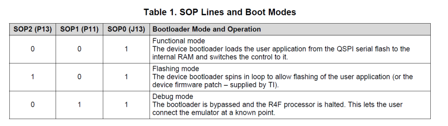
I am interfacing the TCA9539 I2C based I/O Expander with ESP32 MCU and IWR6843 mmWave sensor. I have developed an application to check the functional mode or flashing mode in mmWave sensor using Sense On Power(SOP) pins. These SOP pins are connected to SOP[0]-P04, SOP[2]-P05, and SOP[3]- P06. I have the I2C address (0x74), but I'm looking for an I2C register address to enable the SOP pins. I have checked the TCA9539 datasheet, but I could not find the register address. Please help me to find the register address.

Regards,

Srikanth

  • Srikanth,

    You've correctly identified the device's address, assuming you've pulled A1 and A0 to be 0:

    1   1   1   0   1   A1   A0

    I am assuming you're asking for the register addresses that would go in the Control Register. Table 3 in the TCA9539 datasheet shows a breakdown of the control register values to access the Input Port Registers, Output Port Registers, Polarity Inversion Registers, and Configuration Registers.

    In order to set particular Px pins as outputs, you'll need to set the corresponding value in the Configuration Register to 0. By default, the bits are set to 1 as all ports are defaulted to inputs. The Configuration Register for P0, which includes P04, P05, and P06, is 0x06, or 000001102.

    After setting these pins as outputs, you'll need to set their output value using the Output Port Registers. By default, the bits are set to 1, representing logic high. the Output Port Register for P0, which includes P04, P05, and P06, is 0x02, or 000000102.

    Best,

    Danny

  • Thanks for your quick response.

    Please can you see the below two screenshots for your reference?  the first screenshot is code, I am passing the register address like this. the way I'm doing is correct or wrong. if any mistakes please correct me. the second screenshot tells you the modes. Now my question is based on these two screenshots, tell me how to enable the functional mode using SOP pins and tell me the address.


    Thanks & Regards,

    Srikanth

  • In the previous conversion, I missed attachments. Please refer to the screenshots.

    Regards,

    Srikanth

  • Srikanth,

     Could you please show connection diagram through block diagram to understand the setup?

    Do you need help in TCA9539 or IWR6843 sensor device help?

    Thanks and regards,

    CHETHAN KUMAR Y.B.