Other Parts Discussed in Thread: ADS1292, ADS1298, , ADS1292R
Hello TI application engineer, (forward Ticket CS0318282 , support by TI Danilo R. Austria Jr. Texas Instruments Customer Support)
--------------------------
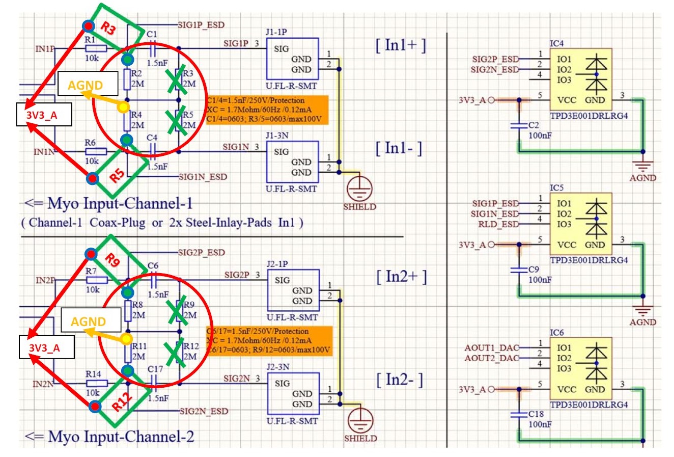
we have an urgent problem with TI ESD protection diode array TPD3E001DRLR for ADS1292 and ADS1298 analogue input interface. See Attachment picture. In our application our analogue data line will be downsize from +1,65V-DC to +0,8V-DC Error-Voltage !! ( 3v3 -> 4M7 -> Data +1.65V -> 4M7 -> GND). Reason is the connection to ESD-diodes only. We could not understand these effects.
Die ADC-Input must be set to +1,65V-DC middle Voltage for AD-conversion 0V-AC ot 2,5v-AC.
We need urgently an application engineer information about these problem. We wait for start 3 Redesigns with these ESD Application. Attachments:
- EMG-Myo-Interface Probe-DC Diodenarry 29-10-2020.jpg ;
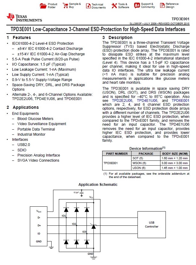
- TPD3E001 ESD-Protection 3-Channel Texas.pdf
- ADS1292r_Shield - Application Circuit PROTOCENTRAL 06-2017.pdf
Best regards A.Schulz 02.11.2020 Vincent-Systems, Germany
EMG-Myo-Interface Proble-DC Diodenarry 29-10-2020.jpg

TPD3E001 ESD-Protection 3-Channel Texas.pdf
ADS1292r_Shield - Application Circuit PROTOCENTRAL 06-2017.pdf