This thread has been locked.

If you have a related question, please click the "Ask a related question" button in the top right corner. The newly created question will be automatically linked to this question.

DP83TD510E-EVM: Cannot establish a successful SPE link (no Pings or Data Tx/Rx between devices)

Part Number: DP83TD510E-EVM
Other Parts Discussed in Thread: DP83822I

Hello Texas Instruments team,


We recently purchased two DP83TD510E-EVM boards for evaluation in hope to migrate our Ethernet products over SPE.

We would like to connect 2 x EVM boards via SPE and communicate with a laptop at each end of the RJ45 connectors and run a Jperf speed/network test

Have run through the Board Setup process in the User Guide.

  • External 12V DC Supply connected to J12, total I ~ 0.08A for 2 boards.
  • Measured all onboard supply rails are fine.
  • We have set both our boards, following User Guide Section 3.2.1 to RMII Master Mode for DP83TD510 providing 50Mhz Clock to DP83822 (Slave) via R149 (PCB Factory Default)
  • LED_0 is strapped low at J20 on both of the EVM boards.
  • SPE link cable 1m twisted pair

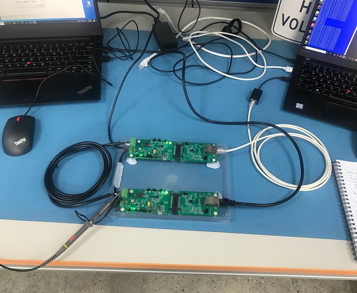
The following is our image details our setup:


We have also downloaded the USB2MDIO Tool to downloaded one scripts at a time that we discovered via the forum post, with no success in linking between boards A & B.

Combinations we tried below:

DP83TD510E-EVM - Board [A]

DP83TD510E-EVM - Board [B]

AutoNegotiation_Initialization.txt   

AutoNegotiation_Initialization.txt   

Force_1Vpp_Master_Init.txt

Force_1Vpp_Slave_Init.txt

Force_2v4Vpp_Master_Init.txt

Force_2v4Vpp_Slave_Init.txt


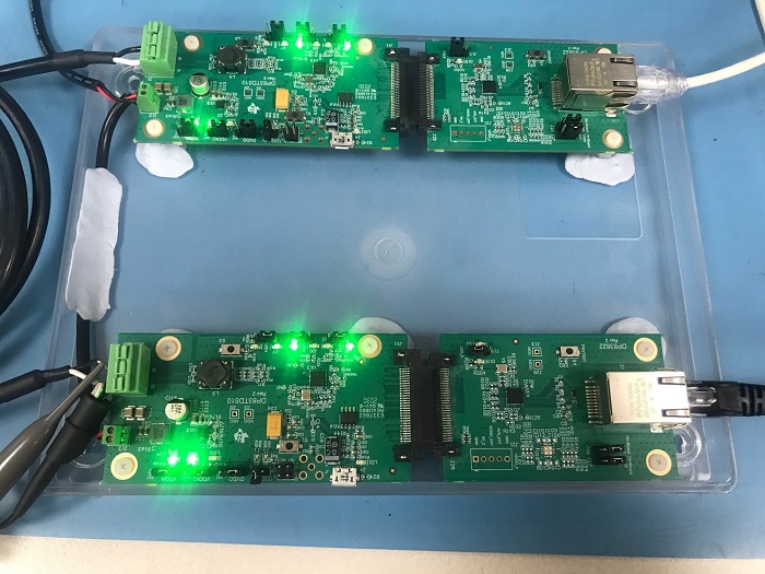
Both RJ45 Jack Green LED illuminates & LED (D15) turns OFF, when link to laptops are successful, providing an Ethernet link @ 10Mbps.

On the SPE board we see LED_1 illuminate on power up, LED_0 only turns on occasionally for what seems to be a few seconds before it drops off again. (See Image below)

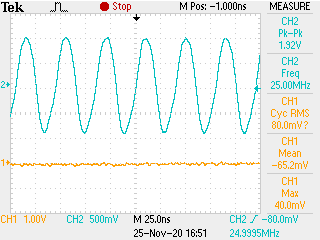
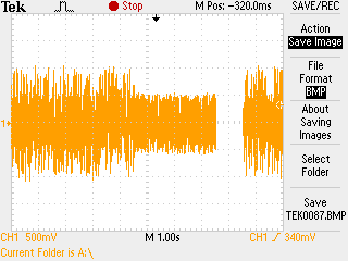
Below is a zoomed out CRO snapshot of the SPE pk-pk when there is a link LED_1 present for a few seconds before it drops off, and the pk-pk of this signal goes down to 1V, and then it continues to attempt again.

Note: Disregard the gap in the signal, due to shifting the screen cap horizontally.

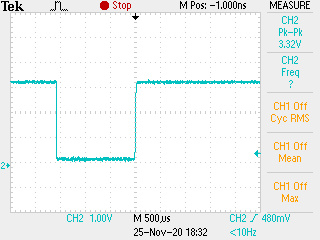
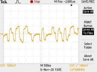
Another zoomed in screen cap below, when there was no link LED_1 present:

What could we be missing here to achieve SPE Link between the devices?

Question, do we need to set 1 x EVM to RMII Master & the other EVM to RMII Slave in order to pair the two together?

Which means populating,/removing resistor straps detailed in section 3.2.2 for EVM Board (B)?


Thanks in advance,


Daniel Haddad

Engineering Manager

Pixel Technologies

  • Hi Daniel,

    We are taking a look at the issue and will get back to you by Tuesday next week.

    -Regards

    Aniruddha

  • Hi Aniruddha,

    Great, looking forward to it.

    Kind Regards,

    Daniel Haddad

  • Hi Daniel,

    We reviewed the information that you have provided and the older forum post that you are referring to. To confirm, you used the text files as-is with no changes from the forum post? When you are using the USB2MDIO software did you select "No" for Extended Register settings when using the Force mode scripts?

    -Regards

    Aniruddha

  • Hi Aniruddha,

    Thanks for coming back.

    Correct, we used the Text files as is (No changes applied)

    Yes i forgot to mention, for all Force Scripts (Extended Register = No), whilst when we tried the Auto-Negotiation script on each board we selected (Extended Register = Yes)

    I read on forum post that toggling S3 will return PHY back to factory default, so this is what we did before each script was run.

    In regards to my previous query, will there be a requirement to set;

    Board [A]  to RMII Master

    Board [B]  to RMII Slave

    In order to pair the two boards together?

    I understand both are set to RMII Master(Factory Default), which provides the 50Mhz clock to the DP83822I, but is this also required before downloading the Master_Init and Slave_Init scripts?

    Just to confirm this will mean populating,/removing resistor straps detailed in section 3.2.2 for EVM Board (B)..?

    If above is not required, what will be our next step?

    Happy to measure any points in circuits, if you would like me to verify and come back with some results or any other steps you would like us to take.

    Regards,

    Daniel 

  • Hi Daniel,

    Changing the DP83TD510E-EVM to RMII slave is not required. The boards are configured to be RMII Master by default and provide clock output to DP83822 which is in RMII slave. Both boards A and B should be left in their default hardware configuration when try all the scripts. If you have made any hardware changes then I would recommend changing the boards back to the default state and trying again.

    As next step, can you provide register read out for 0x0, 0x10, 0x11, 0x12, 0x13, 0x17, 0x18, 0x19, 0x200, 0x201, 0x461, 0x462, 0x467, and 0x468? Please provide the register dump for both boards A and B when they are connected to each other but the link is down.

    In this situation do you ever see the link be stable for a long time? If yes, please also provide the register dump when the link is stable.

    -Regards

    Aniruddha

  • Hi Aniruddha,

    Thanks for your reply, we haven't made any modifications to boards A or B, both are in their default RMII Master state.

    Before posting my register readout results today I thought I'd give it one more go, this time trying something a little different I decided on using the USB-MDIO tool on each laptop, with each connected to its own EVM board via separate USB cables.

    After re-writing the Auto-Neg script to both Boards A & B and confirming each register readout, I noticed the links were connected and remained connected.

    NOTE: This was because I had a USB cable powering boards A and B board, in addition to the 12V DC supply and shunt configuration detailed in section 2.3 and 3.11 respectively.

    It didn’t matter if I closed the USB Port via the USB-MDIO software, I just needed to keep the USB cable connected to each board to keep the link up.

    (Keeping in mind J9 Shunt was removed in this situation)

    ** I will have a bit more time to review the schematic tomorrow and how power is distributed in-circuit to determine why this was required)

    Something else to note, sometimes after writing the scripts, it would require putting the DP83822I into reset by pressing S4 and releasing it again to establish RJ45 link (This link did not always come up).

    Is the above behavior normal or could I be mis-interpreting something in the EVM guide?

    On to the testing, pings were now coming through with a time of 1ms and JPerf bandwidth tests between both boards were also successful.

    I ran a few different speed tests and also connected my laptop through the SPE connection picking up some 1080p60fps content via Youtube, which worked well.

    For long line testing we used CAT6 UTP Reel, which I had a total of 250 meters. I linked up the solid core pairs at each end of the 250m reel to create 500m, 750m and 1000m.

    All was successful and working well up to 750m using the Auto-neg script, with SPE signal voltage pk-pk a little over 1V.

    Register readouts below:

    BOARD A

    Script: AutoNegotiation_Initialization.txt    

    SPE Link LED0 is ON

    BOARD B

    Script: AutoNegotiation_Initialization.txt   

    SPE Link LED0 is ON

    RegisterDumpScript_1.txt file is open...

    Register 0000 is: 1100

    Register 0010 is: 0001

    Register 0011 is: 002A

    Register 0012 is: 2000

    Register 0013 is: 2300

    Register 0017 is: 4025

    Register 0018 is: 0043

    Register 0019 is: 0000

    Register 0200 is: 0000

    Register 0201 is: 0000

    Register 0461 is: 0005

    Register 0462 is: 0000

    Register 0467 is: 0086

    Register 0468 is: 0000

    End of file.

     When attempting 1000m, a link could not be established, on a side note we also tried using the Force 2.4V scripts although, no success.

    Register readouts below:

    BOARD A

    Script: AutoNegotiation_Initialization.txt    

    SPE Link LED0 is OFF

    BOARD B

    Script: AutoNegotiation_Initialization.txt

    SPE Link LED0 is OFF

    RegisterDumpScript_1.txt file is open...   

    Register 0000 is: 1100

    Register 0010 is: 0000

    Register 0011 is: 002A

    Register 0012 is: 0000

    Register 0013 is: 0000

    Register 0017 is: 4021

    Register 0018 is: 0043

    Register 0019 is: 0000

    Register 0200 is: 0000

    Register 0201 is: 0000

    Register 0461 is: 0005

    Register 0462 is: 0000

    Register 0467 is: 0086

    Register 0468 is: 0000

    End of file.

    RegisterDumpScript_1.txt file is open...   

    Register 0000 is: 1100

    Register 0010 is: 0000

    Register 0011 is: 002A

    Register 0012 is: 2000

    Register 0013 is: 2300

    Register 0017 is: 4021

    Register 0018 is: 0043

    Register 0019 is: 0000

    Register 0200 is: 0000

    Register 0201 is: 0000

    Register 0461 is: 0005

    Register 0462 is: 0000

    Register 0467 is: 0086

    Register 0468 is: 0000

    End of file.

     After some further reading tonight, I found some details in Section 7.4.1 of the datasheet, Table 7-6. Reach Selection Strap, happy to explore this further.

    Although briefly will the AutoNegotiation_Initialization.txt script enable us to achieve +1000m long reach and produce a 2.4-V p2p signal, and establish a link?

    Any assistance would be appreciated.

    Ps. We are also exploring a few different site installation use cases, and were wondering how SPE would perform over let's say an available, but not utilized CAT3 backbone of 25 Pair 24AWG existing voice trunk infrastructure with 25 SPE links running simultaneously.

    Would this technology work, what are the limitations, immunity and will it cause any cross-talk or interference?

    Kind regards,

    Daniel

  • Hi Daniel,

    The powering scheme from 2.3 and 3.1.1 of the user's guide will configure the EVM to be powered by external DC supply. The USB connection would only be used for the register communication. As such, maintaining an active COM port is not required to keep the link active.

    When DP83822 does not link up, can you check if you still have register access to DP83822 & also check if it is sending FLPs on the Ethernet cable using a oscilloscope.

    From the register settings, i do not see anything unusual. I will need to double check if Cat 6 cable has been evaluate for 1000m link. How are you connecting 250m cables to each other? Is there a interconnect or are you manually soldering them to each other?

    -Regards

    Aniruddha

  • Hi Aniruddha,

    Apologies i have been caught up on a few different projects this week.

    I will need to investigate the method of keeping these EVM boards linking from only the external 12V Supply, I've got a suspicion that it could be related to registers holding their values but will need to do more diagnosis around this.

    My steps are as follows;

    1. Power up boards with 12V DC

    2. Connect USB and program Autoneg scripts into both boards, Close Port, keep USB Cables plugged in.

    3. SPE links and i get 10Mbps data transfer.

    4. Remove USB cable from any of the boards and I immediately loose SPE link and data transfer.

    5. Connect USB cable back into EVM board, I must re-download the Auto-Neg script to establish a link again.

    I will need to probe the FLP's next week sometime, and will come back to you in regards to Etehrnet not lining without resetting one board using S4.

    Look forward to your responce on cable type/length around multiple CAT3/5/6 cabling.

    Our interconnect is via 3.81mm green terminal plugs, and there are solid connections, DC resistance measured as follows;

    - 250m = 19 Ohms

    - 1000m = 74 Ohms

    Also it would help if we could get a Schematic export in PDF that allows us to zoom/search the parts and designators to assist with navigating the design and fault finding.

    Its a little cumbersome trying to do so with the screen shot schematics published in the EVM, being a little pixellated and non-searchable, would this be possible?

    Regards,

    Daniel

  • Hi Daniel,

    In your setup, after removing USB cable do you just loose link or the power to the 510 device goes down? If you are supplying power through 12V DC source then removing USB cable should not power down the PHY. As a sanity check, can you confirm if the shunt connections match with section 3.1.1 of the user's guide. For 12V DC source, shunt J9 needs to be removed.

    To check that the 510 PHY is still on after you remove the USB cable, can you check the clock out pin to see if the output clock is available? You can also probe XI/XO for the same check.

    For the pdf schematics, I will get back to you shortly.

    -Regards

    Aniruddha 

  • Hi Aniruddha, 

    No power loss, only the SPE link is lost when USB cable is removed.

    Images below for shunt connections for 12V DC external power as detailed in section 3.1.1


    Clock is available when both SPE Link is Up and Down, see screen caps below;

    XI (25Mhz) - Board A & B 

    XO (25Mhz) - Board A & B


    Not sure if this could point to something, although I noticed a difference in Vpk-pk between boards is 900mV at RX_CLK-1 (50Mhz) 

    When SPE Link is Up.

    Board A


    Board B

    To re-establish an SPE link as mentioned, I must re-connect USB and download Auto-Neg Script.

    It seems the SPE PHY registered are being RESET when I remove the USB cable.


    The 510E datasheet, and it states the following;

    Measuring the RESET pin at S3, whilst removing the USB cable the signal asserts itself low for 1.5ms. See screen cap below;


    This could explain why the Internal 510E PHY registers are being reset to default and requires the Auto-Neg script to be downloaded each time.

    Hope there is enough data here to determine why this could be occurring.

    Hope to hear from you soon, thanks.


    Regards,

    Daniel


  • Hi Aniruddha,

    Have you had a chance to look at the findings above?

    Kind Regards,

    Daniel

  • Hi Daniel,

    I am reviewing the information that you have sent and will send you an update by Friday.

    -Regards

    Aniruddha

  • Hi Aniruddha,

    Do you think there could be something wrong on a hardware level with one or both of the EVM boards we've received?

    Should we be looking at getting an exchange or do you think there might be something else on a firmware/process level we need to look at first? 

    We are very keen to start looking at designing this solution in, just need to ensure its ready across all aspects before we start development.

    Also we have a few queries;

    • is there a PoDL solution Ti are looking to offer both at the Hub and the Device? if not is there an ETA on a solution we can plan towards?
    • Is there an available MAC controller that Ti offer which would allow us to design a multiport SPE hub, lets say 5 ports, 4 x SPE and 1 x RJ45 that would allow for four SPE "Star network" links to connect back into network via RJ45? 

    Thanks in advance,

    Daniel

  • Hi Daniel,

    Thanks for sending in the previous feedback. The RESET pin toggling low would definitely wipe out the register settings. It is weird that it happens during USB disconnect. The Reset pin of the PHY is connected to the on-board microcontroller through a level shifter. I am currently checking if there is anything in in the microcontroller or the level shifter that can cause this disconnect. As discussed before, please find the EVM schematics attached below.

    DP83TD510E-EVM-Schematic.PDF

    For the PoDL solution, since it deals with future board/product design we can take this discussion over E2E private chat. For the MAC controller, do you have a local TI FAE or TSR contact? They can help you get in touch with the right TI team. If not, let me know and I can try to find the correct E2E forum where you can reach out. 

    -Regards

    Aniruddha

  • Hi Aniruddha,

    Thanks for confirming the reset of the PHY registered is caused via the onboard MSP430 MCU, look forward to a fix on this.

    Appreciate you sending through the schematic also, controller ports and component designators are much more readable this will assist in following the signal paths through.

    Yes we caught up with our friends at Arrow Electronics today, and discussed the MAC controller with the FAEs, they will do some research and come back with a solution.

    I will send you a E2E private request, looking forward to discussing the upcoming PoDL solution with you also.

    Cheers,

    Daniel

  • Hi Daniel,

    We are still working on narrowing down the reason for this reset pulse. I will follow up once we get a resolution. For the PoDL, I will reply on the private chat.

    -Regards

    Aniruddha