This thread has been locked.

If you have a related question, please click the "Ask a related question" button in the top right corner. The newly created question will be automatically linked to this question.

TUSB542: TUSB542RWQ

Part Number: TUSB542
Other Parts Discussed in Thread: TUSB322I

dear

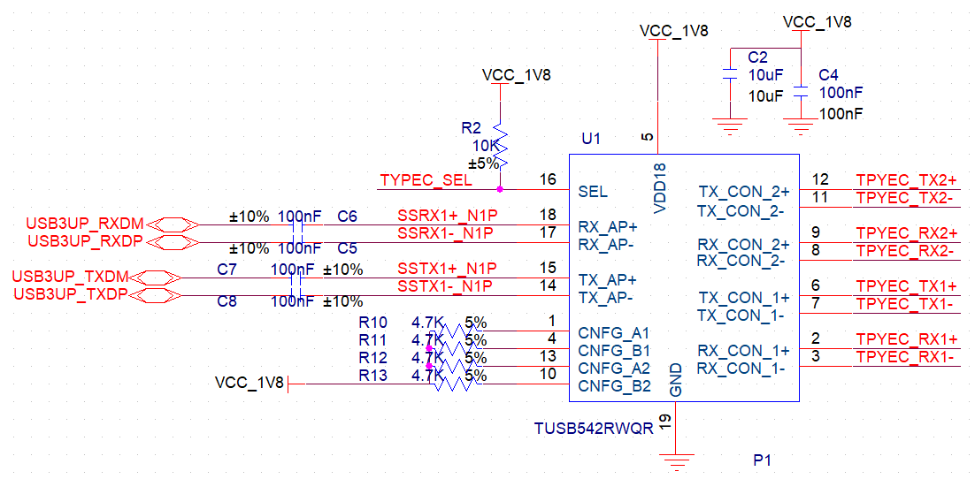
 Pin define in TUSB542RWQ datasheet  show as below

However , Pin define is different  in TUSB542RWQ product information which find on the official website show as below,which is correct?


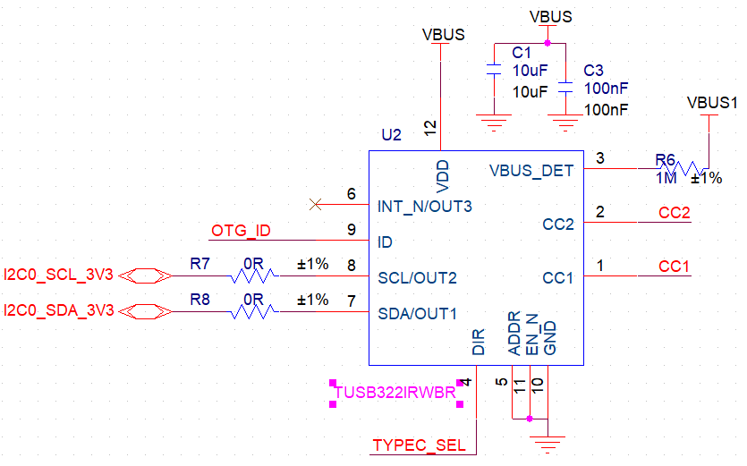
The circuit diagram of TUSB322IRWBR is as follows. After connecting the USB with forward (reverse) insertion, CC1=0, CC2=0.4V, and TYPEC_SEL=0.Backplug (positive plug) connection USB,CC1=0.4V, CC2=0, TYPEC_SEL=1.8V;

The chip can realize DIR pin high and low level selection;But USB 3.0 has not been conduction, plug USB in any case can only identify to USB 2.0, other circuits are normal, can be sure, the problem is in the two chips;

 any  advise ? thanks in advance

  • Hi,

    Please refer to the pin definition in the datasheet for TUSB542RWQ

    It seems that TUSB542 is not muxed in the right direction when USB-C is connected preventing USB 3 enumeration. The polarity of SEL pin is different from the polarity of the DIR pin.

    SEL pin of TUSB542
    H (Conn Position 1)
    L (Conn Position 2)

    DIR pin of TUSB322i:
    H (Conn Position 2)
    L (Conn Position 1)

    If possible I recommend connecting CC1 -> CC2 and CC2 -> CC1 on the TUSB322I pins to help correct this difference in polarity.

    TX1/2 should be AC coupled with 220nF and RX1/2 should be AC coupled with 330 nF. This is highly recommended when AC coupling a redriver to a USB-C connector.

  • dear Malik Barton57

    Thank for your reply

      I have followed your suggestion,the capacitor part has been modified. CC1 and CC2 pins have been cross-switched. The new version is connected interchangeably, but it is still not recognized.

    any other advise?thanks in advance

  • Hi CS,

    Can you give more details on your application, is it a UFP, DFP or DRP? Are you using TUSB322I in I2C or GPIO mode? I noticed you left INT_N unconnected for I2C operation however this signal should be used to indicate to MCU or AP that TUSB322I should be read, if I2C mdoe is used .

    What kind of device are you testing with? Can you try probing on TX1/2 or RX1/2 and look for LFPS signal when the USB-C port is connected? Please make sure to use a high impedance probe.

  • Thanks for you reply!

        In UFP mode, ADDR is in NC state, so the chip design works in GPIO mode. ISDA SCL pin has two pull-up resistors. When using CPIO mode, INT_N pin does not need to be in NC state.A lot of thinking, are not sure what went wrong!

    thanks in advance 

  • Hi,

    In the above image provided ADDR is shorted to ground. Is this the latest schematic? 

    Since your application is UFP only we should look for the following with a high speed scope:

    • When connected Vbus should go high to 5V. Vbus should be provided by the connected DFP or DRP when the connected is made.
    • If TUSB542 is configured correctly then you should see LFPS signaling when the connection is first made. Please probe RX1 or RX 2 based on the flip or "no flip" orientations.
    • Ensure TUSB542 is powered correctly at the time of connection.