This thread has been locked.

If you have a related question, please click the "Ask a related question" button in the top right corner. The newly created question will be automatically linked to this question.

TCA9535: INT pin is not pulling up

Part Number: TCA9535

Hi Team,

I would like to ask for your assistance regarding the situation of our customer below with INT pin of TCA9535:


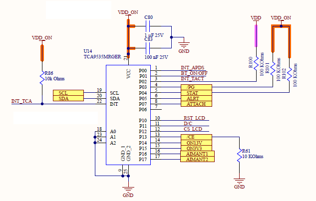
All Port 0 are in input and all Port 1 are in the output.
For the input port 0, they have an external R pull up of 100k.
Some of these R are tied to the same VDD of the TCA9535 (VDD_ON), and 2 of these are tie to an other VDD (cut with a load switch IC).
In the beginning, VDD is LOW, the INT pin work normally, but when they switch on the VDD, the INT pin don't work, and keep LOW even if the input change.

Please let me know your input in the above schematic.

Thanks,

Jonathan

  • INT goes low (not high) when an input changes. If INT stays low, then the interrupt is never cleared, or some input keeps changing.

    What are the values of VDD_ON and VDD?

    Is input P06 really open?

  • Jonathan,

    Clemens is correct. Note that the INT pin has an open-drain structure, and that it can only pull down. It cannot pull up. This is why it requires an external pull-up resistor (usually about 10 kΩ).

    If you leave P06 floating, the device will be constantly interpreting this floating input as changing, thus constantly causing it to trigger an interrupt. You should connect this to your voltage rail via a pull-up resistor (or, if this is impossible, you can set it as an output).

    Please note that the horizontal bar above a pin name, such as in INT, indicates that it exhibits inverted logic. Here, a logic low represents an interrupt event. The pull-down is released when the interrupt is cleared.

    Best,

    Danny

  • Hi Danny and Clemens,

    Thank you for your great support in this thread.

    Upon sharing your inputs with the customer, here's the answer I got:

    At power up, VDD_ON = 3.3V and VDD = 0V
    INT is low at power up (They have a small HIGH pulse of about 6 ms).

    They try to put P06 in output, and is the same problem.
    They always have INT low at power up.

    Please let me know your comment.

    Regards,

    Jonathan

  • Jonathan,

    Thanks for following up!

    When an interrupt is cleared, you should expect it to be released high. Any change in an input pin causes INT to be pulled low until the condition is cleared. The TCA9535 does not contain the capability of driving/latching INT high under any circumstance (hence the need for an external pull-up). This is why it is expected behavior to see INT low after VDD changes state.

    Please try reading from the input port registers (Register 0 and Register 1), since this clears the interrupt condition. As long as all of the input pins remain unchanged after this read, you should expect INT to be high. Once P02 or any other input Pxx changes state, you should see INT pulled low again by the device.

    Would you be able to check and see if the customer can replicate this condition?

    Best,

    Danny

  • Hello Danny,

    After sharing your information above to our customer, here's the answer I got from them:

    If they have VDD_ON = VDD = High at the power up, it work fine, they have INT High and it goes Low when they have P01 that chnage state.
    But When at power up VDD_ON = High and VDD = LOW (so P00 and P02 are Low) the INT stay Low, even if they read the state.
    Here is the code of initialization:
    TCA9535_write(I2C0, TCA9535_ADDW, CONFIGUREPORT0, 0xBF); // P0 = tout en input sauf P0.6 en output (flottant)
    TCA9535_write(I2C0, TCA9535_ADDW, CONFIGUREPORT1, 0x00); // P1 = tout en output
    TCA9535_write(I2C0, TCA9535_ADDW, OUTPORT1, 0x00); // P1 = tout à 0
    TCA9535_read(I2C0, TCA9535_ADDR, &port0, INPUTPORT0); // read P0

    After that, when VDD is Low, INT stay Low. They think it's because P00 and P02 are Low. Are you sure the INT pin change when a edge change and not on a level ?


    Regards,

    Jonathan

  • Jonathan,

    Thanks for the clarification, I see what you're describing. I'd like to help figure out what's causing this behavior.

    To answer your question directly: yes, the interrupt is triggered by any rising or falling edge of the inputs in the input mode, and it lasts until the data on the port changes back to the original setting or when data is read from the Input Port register (as it appears to be the case in the code you've provided). This being said, we should expect to see the INT signal reset when P0 is read via Register 0. I believe we are on the same page here.

    To help figure out what's going on, I have a few questions:

    • Is VDD powering any other devices aside from P02 on this device?
    • While INT is pulled down during VDD = 0, do multiple repeated reads of Register 0 always return the same data, or does it change each time it is read?
    • Are any of the other input pins connected to a high-impedance connection, like an open-drain output or another GPIO pin for example?

    Additionally, if you'd rather continue this conversation over email, you can reach me via email at d-bacic@ti.com (also found by clicking my E2E account name). Any communication method is perfectly fine with me.

    Best,

    Danny