This thread has been locked.

If you have a related question, please click the "Ask a related question" button in the top right corner. The newly created question will be automatically linked to this question.

TPS65982: I've designed the USB Hub using TPS65982, and trying to send DP signal from the hub to DP TO LVDS board.

Part Number: TPS65982
Other Parts Discussed in Thread: TPS65987D, TPS65987

Hello,

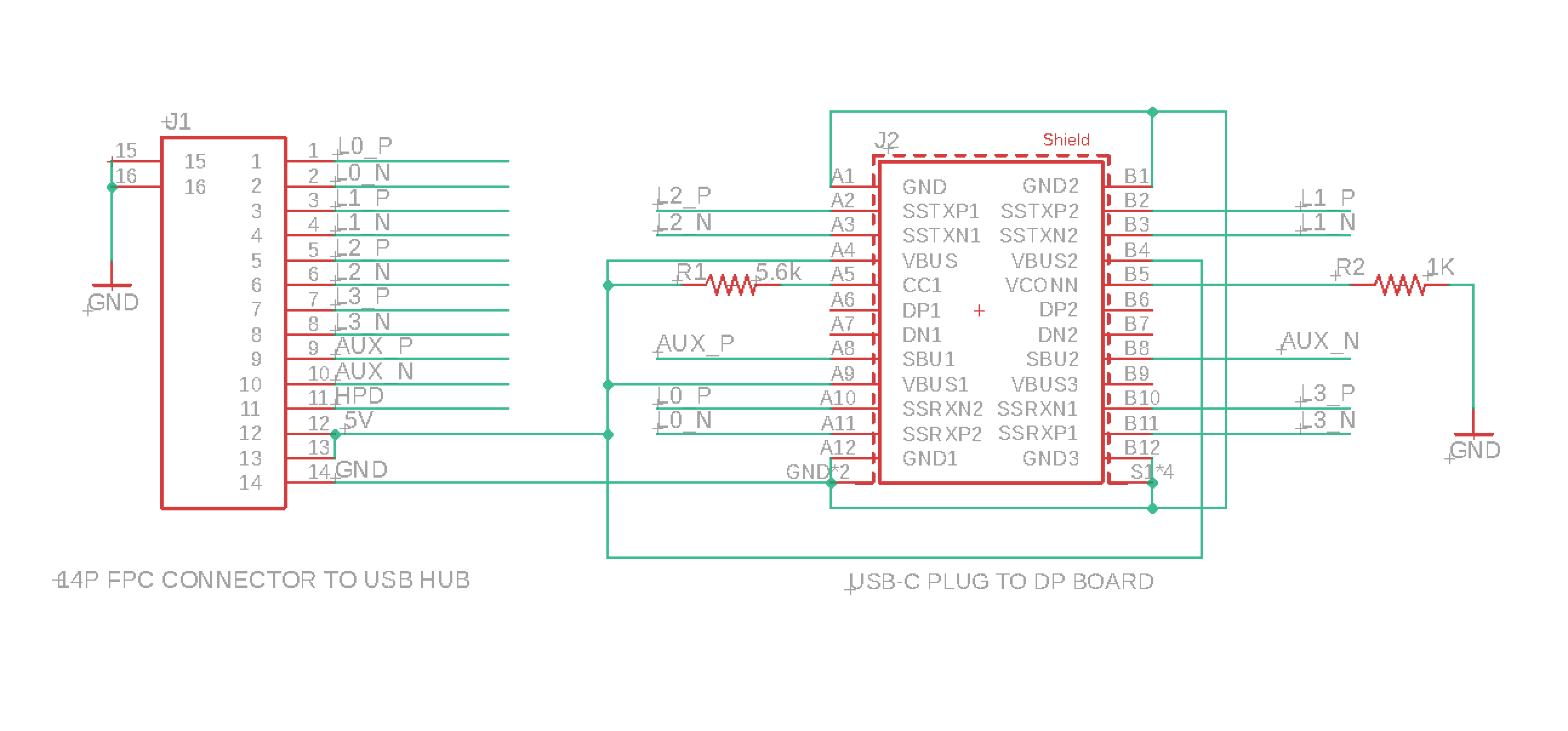
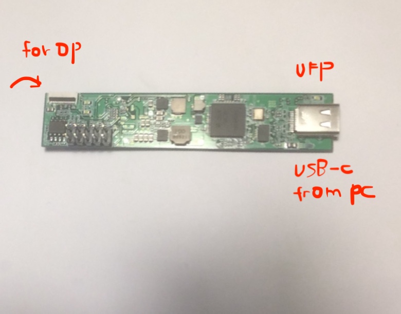
I've designed the USB Hub using TPS65982. It has got DP out via 14 pins FPC connector like below.

and I was planning to make custom DP TO LVDS board to get this signal, which is not quite possible due to my schedule. 

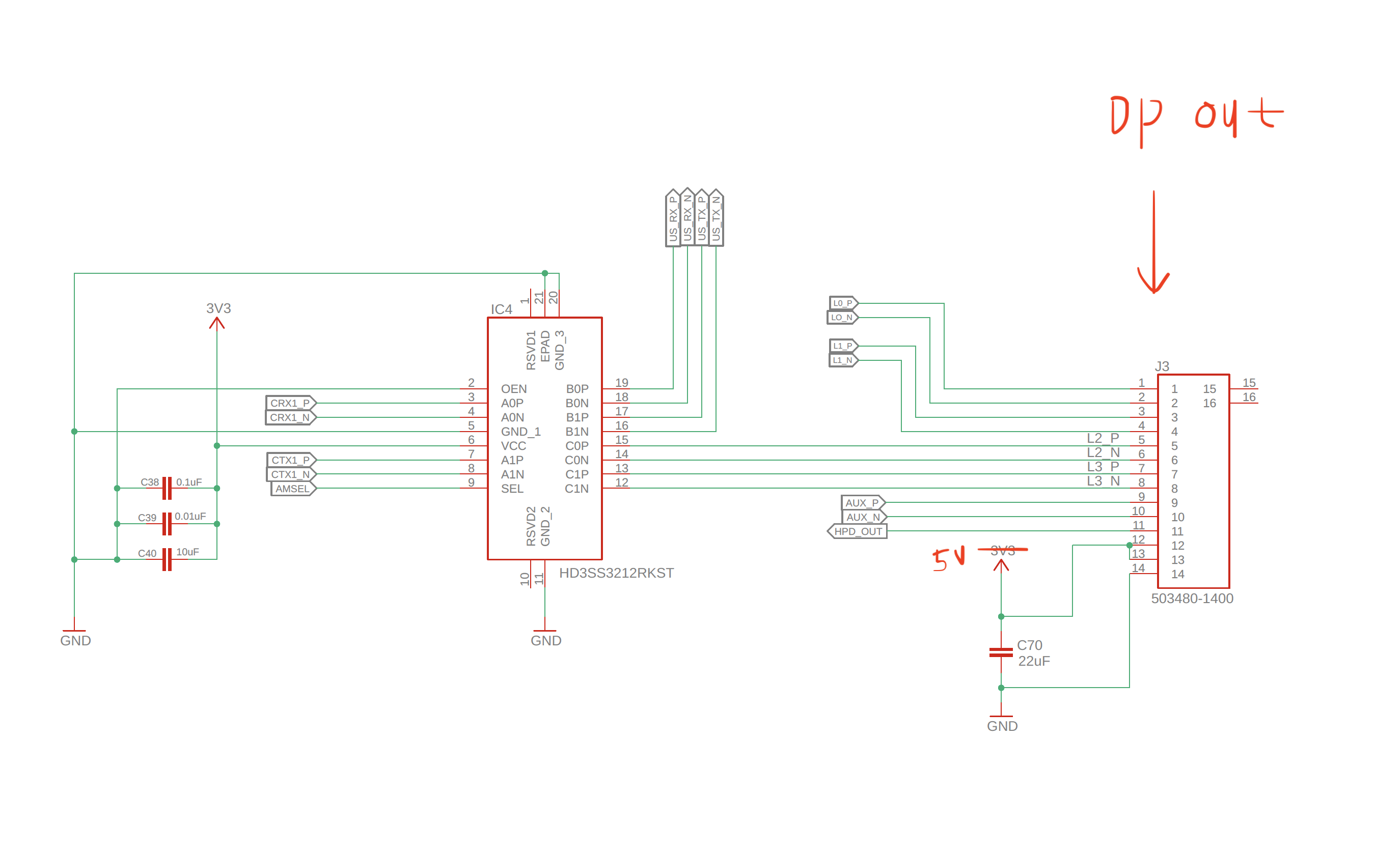
So I'm going to use DP TO LVDS board provided by Chiness company. the board has USB-C input.

For connecting those boards, I need to design kind of converter between them. 

I wonder whether the converter needs PD controller to be connected to DP TO LVDS board via USB-C.

or can I just use pull up resistor on CC pins and wire those DP signal from hub to USB - C plug on the converter.

Thank you!

Best,

WOOJUN

  • Hi Woojun,

    Can you make a block diagram of what you are making/using here? 

    Thanks,

    Emma

  • Hi Emma,

    Thanks for the reply! 

    the basic idea of my board is like below.

    basically, my board has got usb 3.0 function and DP out.  The DP signal(DP-4l lane) can be out via 14p FPC connector like below.

    The problem is the DP TO LVDS board has got USB-C receptacle, whereas my test board has got 14p connector. 
    So i would like to ask whether it is going to be possible to connect those boards by designing some kind of convertor in between without additional PD controller chip.
    I've made a schematic of the converter. excuse i'm a software guy.
      
    Do you think this converter make sense? or Do I need to have additional PD controller chip dealing with DP TO USB-C connection?
    Please let me know if you need more explanation.
    Thank you very much!
    Best,
    WOOJUN

  • Hi, Emma

    If you need more info about my situation, Please let me know. 

    It will be great if you can give some hints about solving this issue.

    Best,

    WOOJUN

  • Hi Woojun,

    Do you need to negotiate a DP alternate mode with a downstream device? If not, you can pass through the DP signals and do not need a DP controller. Basically if you want to connect an external system that has its own DP architecture and a Type-C port, then you will need to add a PD controller.

    Thanks,

    Emma

  • Hi Emma,

    Thanks for your reply. I think the display board has its own DP architecture and a Type-C port. 

    The board has got Lontium 7211B, which is Type-C/DP1.2 to Quad-port LVDS controller.

    in this case, Do I need to have one more TPS65982 to deal with USB-C DFP?  and is there any design I can reference (USB C dock or hub, which has DP output via USB-C port)?

    Thank you very much for your help!

    Best,

    WOOJUN


  • Hi Woojun,

    I am still not quite clear, are you trying to design two systems or one system? If this is all in the same system, you can simply pass through the DP signals. 

    Also, as a note, the TPS65982 is at EOL and is not recommended for new designs. I would recommend doing this design with the next gen part, the TPS65987D. 

    Thanks,

    Emma

  • Hi Emma,

    Basically, it is going to be one system, but for testing the DP to LVDS driver board with my hub, I need to design an extra converter between them,

    after the test, I will redesign the hub.

    The DP to LVDS board I'm going to use has got USB-C port, which means it does PD negotiation and alternate mode negotiation. 

    The problem is my hub doesn't have USB C DFP which can transmit DP video. it only has got DP signal out via 14 pins connector like below.

    it is consists of DP 4 LANES, AUX +/-,  HPD, VCC and GND.

    For designing the hub can transmit DP Video via USB-C DFP, I guess I need one more PD controller.

    1.My question is, how does the two pd controller communicate each other?   Obviously, HPD signal from DP to LVDS driver board should be passed to the host.

    here is the schematic of PD controller part for UFP (TPS65982).

    2.Would it be possible for you to recommend any reference design I can study for this kind use?

    3.  Does HPD signal from a display which has USB C input use SBU as a data path? 

    Thank you very much for your time!

    Best,

    WOOJUN


  • Hi Woojun,

    1. Two PD controllers communicate with one another over the CC lines. The CC lines are used to negotiate a power delivery contract. The super speed lines are used for displayport, and the SBU lines are used for displayport aux channel.

    2. I would recommend checking out the TPS65987EVM. The DP lines are passed through on the expansion connector. There is a helpful EVM tutorial as well as accompanying GUI videos which explain how to configure the firmware. The third GUI video goes over DisplayPort. The TPS65987D is the latest in our USB Type-C PD controllers and will be the best fit for your design.

    3. HPD is sent over CC through DP attention message in DP alternate mode. This app note will explain more of how the DisplayPort alternate mode works. 

    Thanks,

    Emma

  • Hi Emma, 

    I will study the materials you suggest, I think those are very helpful. 

    Also, I will use TPS65987 for the next version. 

    I really appreciate your help throughout. thank you very much!

    Best,

    WOOJUN

  • Hi Woojun,

    No problem, happy to help!

    Emma