Part Number: DS90UB954-Q1
Hello Ti-Team,
We are looking into the following issue using GPIO3/INTB as Input for an e.g 10Hz Signal.
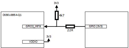
The GPIO/INTB pin is wired as followed:
- If the DS90UB954 is disabled and not initialized, the voltage level on the GPIO path is 3,3V
- As soon as the DS90UB954 is enabled and an 10Hz (3,3V) signal is send to GPIO3/INTB, the high voltage on the left side of the 22R resistor is about 0,7V and on the right hand side of the resistor at about 1V9.
- If the 22R resistor is removed, the voltage on the GPIO3/INTB pin is about 0V (not 3V3 as in standby) and the amplitude of the 10Hz signal is as expected at about 3,3V on the output of the source.
So it seems, the both GPIOs are driving against each other altough the GPIO3/INTB pin is configured by default as input / open drain. All other GPIOs of the DS90UB954 are working well with this 10Hz signal. Are there some registers for the GPIO3/INTB to take special care of to disable e.g. the interrupt?
Thanks for your Support!
Regards
Robert