This thread has been locked.

If you have a related question, please click the "Ask a related question" button in the top right corner. The newly created question will be automatically linked to this question.

SN65DSI84: how to config with dsi input and lvds panel whose timing not exacltly match?

Part Number: SN65DSI84
Other Parts Discussed in Thread: DSI-TUNER

Our dsi config works fine with a dsi-interface panel, and the dsi dphy bitrate is 900Mbps.

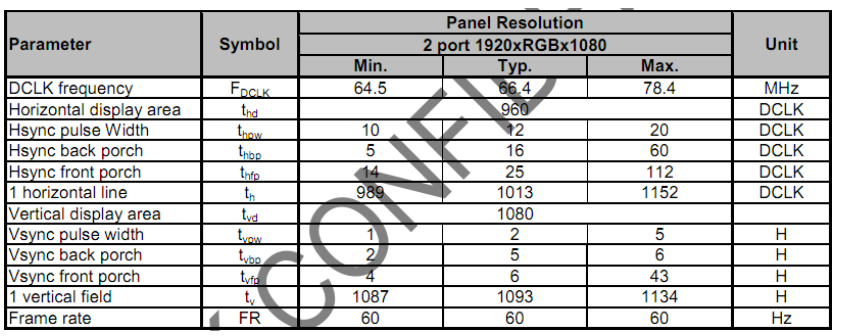
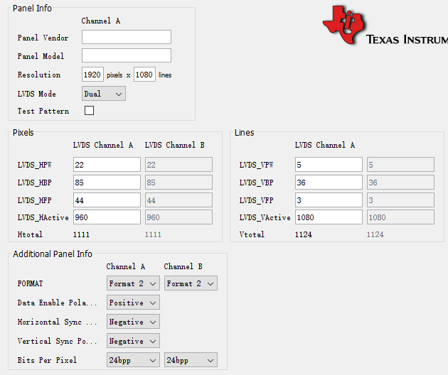
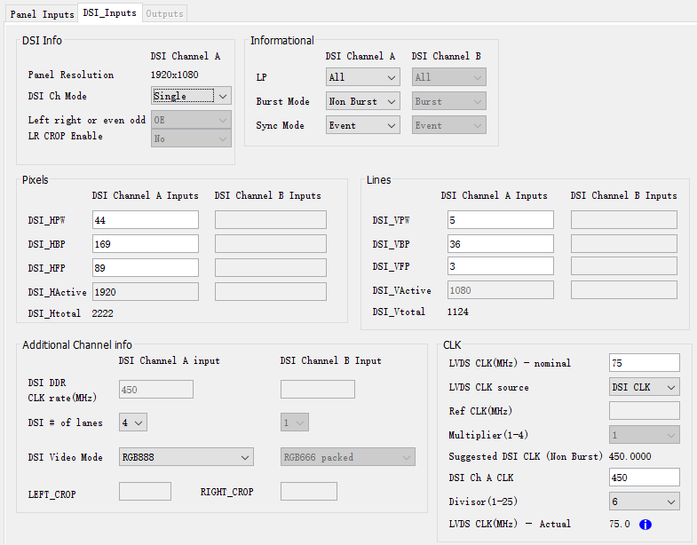
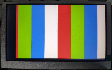
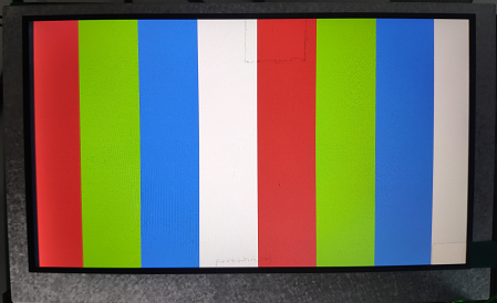
data path is:dsi source (900Mbps) --> sn65dsi94  --> lvds panel

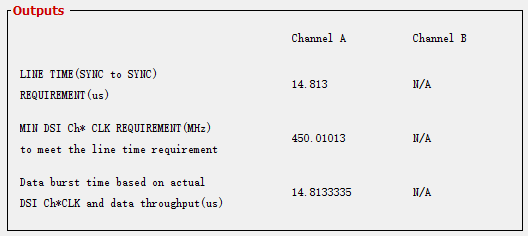
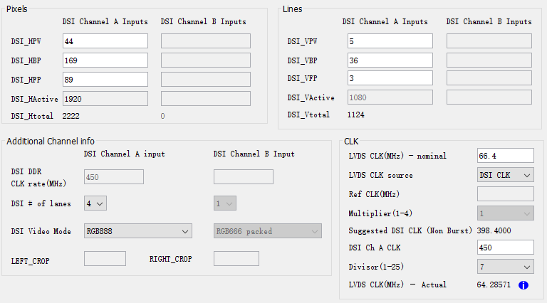
I just can't get the the 2 times in Ouputs window the same.

How can i get the dsi source correctly convert to lvds the panel needed?

Do i have to change the dsi dphy bitrate so that the lvds clk can perfectly match?

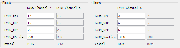
Here is my dsi status configuration, plz help.

Thanks a lot.https://e2e.ti.com/cfs-file/__key/communityserver-discussions-components-files/138/pj5801g02.7z

  • Hi I.K.,

    Thank for help. But following the FAQ didn't resolve my issue.

    This is the panel's timing spec:

    Since the dsi dphy bitrate, which is fixed to 900Mbps, can't be changed.

    Seems only 2 ways to go, but dsi source of neither displayed on the panel:

    1) adjust panel input to meet dsi dphy bitrate, result in perfect match the DSICLK=f(LVDSCLK) equation, and almost the same "LINE TIME(SYNC to SYNC)“ and "Data burst time".  The sn65dsi84 test pattern worked, but dsi source image did not show up after test disabled.

    With Panel Inputs "Test Pattern" option checked, i saw the colorbar on the panel (but there was align issue here?).

    Without the option, nothing displayed, CSR E5 was 0x80,indicated  a hsync or vsync error, here is the dump of all CSRs:

    0000: 35 38 49 53 44 20 20 20 01 00 85 30 00 01 00 00
    0010: 26 00 5a 00 00 00 00 00 6c 00 03 00 00 00 00 00
    0020: 80 07 00 00 00 00 00 00 20 00 00 00 16 00 00 00
    0030: 05 00 00 00 55 00 00 00 00 00 00 00 00 00 00 00
    0040: 00 00 00 00 00 00 00 00 00 00 00 00 00 00 00 00
    0050: 00 00 00 00 00 00 00 00 00 00 00 00 00 00 00 00
    0060: 00 00 00 00 00 00 00 00 00 00 00 00 00 00 00 00
    0070: 00 00 00 00 00 00 00 00 00 00 00 00 00 00 00 00
    0080: 00 00 00 00 00 00 00 00 00 00 00 00 00 00 00 00
    0090: 00 00 00 00 00 00 00 00 00 00 00 00 00 00 00 00
    00a0: 00 00 00 00 00 00 00 00 00 00 00 00 00 00 00 00
    00b0: 00 00 00 00 00 00 00 00 00 00 00 00 00 00 00 00
    00c0: 00 00 00 00 00 00 00 00 00 00 00 00 00 00 00 00
    00d0: 00 00 00 00 00 00 00 00 00 00 00 00 00 00 00 00
    00e0: 00 00 00 00 00 80 00 00 00 00 00 00 00 00 00 00
    00f0: 00 00 00 00 40 00 00 80 00 00 00 00 00 00 00 00

    2) panel input meet panel's typical timing, result in unmatched "LINE TIME(SYNC to SYNC)“ and "Data burst time". 

    The sn65dsi84 test pattern worked, but dsi source image did not show up after test disabled.

    The sn65dsi84 test pattern seems better than that in 1).

    Without "Test Pattern" option checked, CSR E5 was 0x80,same as that in 1).

    Test pattern colorbar showed up, so panel timing, signal polarity, format, bpp seemed ok.

    Which way is more reasonable? Why there was sync error? How can I fix it?

    BTW, can you tell me how to calculate the value of CSR 28?

    Thanks a lot.

    B.R.
    Larry

  • Hi Larry,

    The first set of new settings you used are correct for the DSI84. However, you need to ensure that whatever your DSI source is outputting (DSI CLK frequency, active pixels, blanking pixels), etc. matches exactly with what you've programmed into the DSI84.

    The DSI-Tuner will calculate 0x28 so need to worry about that. 

    Regards,

    I.K. 

  • Hi I.K.,

    I've found why i got CHA_SYNC_ERR, i set CSR.0B.dsi_clk_div to wrong value '0110' (which should be '0101' for 'Divide by 6').

    It's strange that no more colorbar displayed in test mode after i fixed the CSR.0B, nor my own drawing image.

    I've dumped and checked the sn65dsi84's registers carefully, and they are exactly the same as DSI Tuner output (except CSR.0A.b7 and CSR.0D.b1). And no CSR.E5 error bits were set.

    So is it as expected? Or anything can be wrong?

    Thanks a lot.

    B.R.
    Larry

  • Hi Larry,

    You need to check that your DSI source output (not the DSI-Tuner) matches the settings you've programmed into the SN65DSI84. 

    You can also check this FAQ for additional debug steps: https://e2e.ti.com/support/interface/f/138/t/852871 

    Regards,

    I.K. 

  • Hi I.K.,

    After change CSR.1A from 0x03 (DSI Tuner default) to 0x00,both the test pattern and dsi source can display now.

    There was not any description on the termination resistor in the panel's spec, so never had doubt that.

    Thanks for your kind help.

    BTW, i have some DSI Tuner 2.1 using issues you may be interested to know:

    CSR.18 always be 0x6X, no matter what DE/HS/VS setting in the "Panel Inputs" window.