This thread has been locked.

If you have a related question, please click the "Ask a related question" button in the top right corner. The newly created question will be automatically linked to this question.

DP83822H: DP83822 forces the Reset_n to 1.8V

Part Number: DP83822H
Other Parts Discussed in Thread: TMS320F28388D

Hello everyone,

I have a problem with the reset line on a CPU Board.

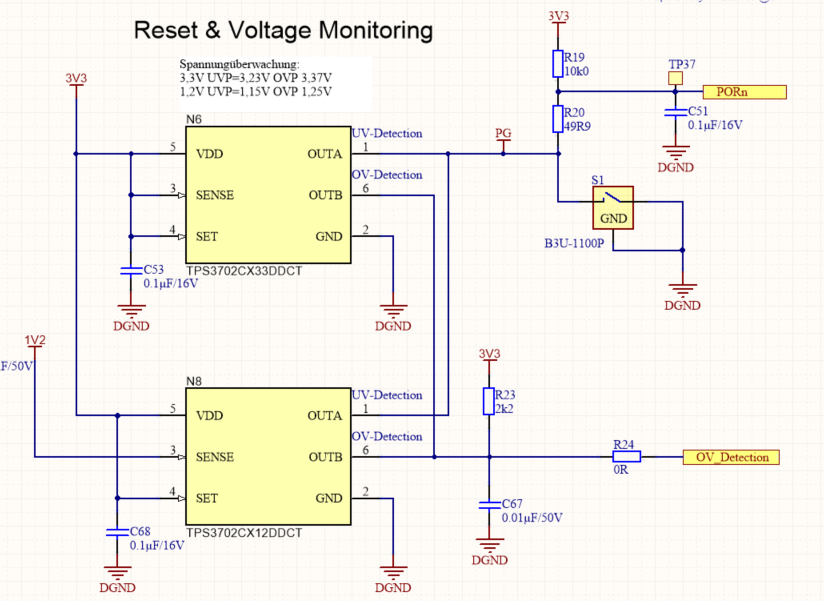
I created an Powergoodsignal with the signals of some DC/DC inverter and two Voltage-monitoring devices (TPS3702CX) with a Pullup Resistor (5k Ohm) to 3.3V and a Pulldown Switch.

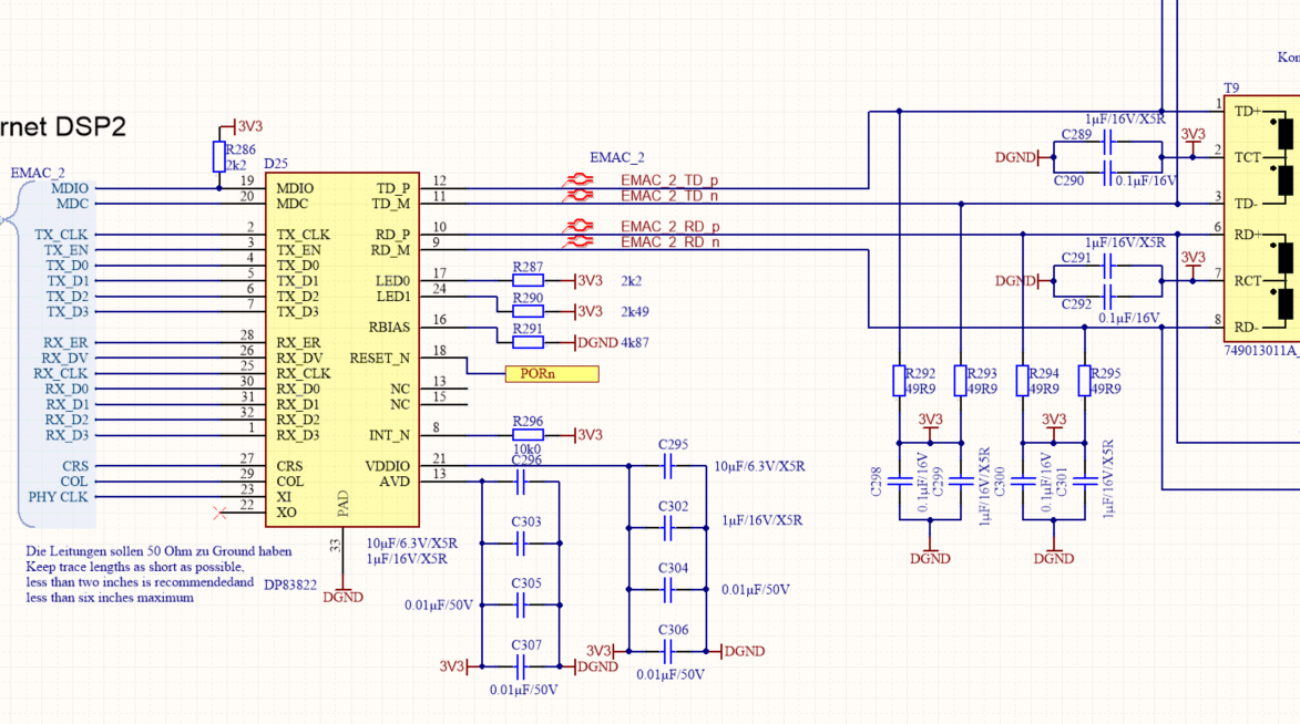
This Part is working well when i disconnect it from a reset line going to various reset pins from DSPs (TMS320F28388D) and PHYs (DP83822) and some others.

The Problem is that the "reset line" is pulled to the voltage of 1.8V.  When i use a 50Ohm Resistor to pull the "reset line" to GND the Voltage drops to 1.6V the current int the resistor must be somewhere around 33mA.

When i connect the "reset line" directly to ground over a switch. I can detect a quick rise in temperature in the "DP83822" starting a 25°C to 45°C in 2 sec.

the Main problem is that the Voltage of the reset line is not pulled to 3.3V.

the second problem is that the components can’t pull down the "reset line" from 1.8V to 0V.

Do anyone have an Idea to solve this Problem?

Thank you

Jan

  • Hi Jan,

    Are you able to share a schematic?

    Thank you,

    Nikhil

  • I can´t share the complete schematic.

    But here are some parts of the Pullup resitor and the Voltagemonitoring with reset button:

    Here is the schematic of a Phy:

    i dismounted the Phys and now the Voltage at the "resetline" (PORn) is correctly pulled to 3.3V.

  • Hi Jan,

    What is the signal on OUTA labeled PG? I do not see the 5kohm resistor mentioned, I see POR pulled up to 3V3 by a 10k resistor next to N6. If I understand correctly, when the PHY reset pin is disconnected from the rest of the reset line connected to other devices, reset is working as expected. However, when the PHY reset is connected to the reset of the other devices, it is not able to reach 3.3V or be pulled down to 0V, is this correct?

    Thank you,

    Nikhil

  • Hi Nikhil,

    thank you for your reply.

     the Label PG (Powergood) goes to three DC/DC "Synchronous Buck Converter" each one to the Powergood-Signal of each DC/DC buck converter.

    parallel to the 10k Resistor (R19) is second 10k Resistor soldered in. to create the 5k Ohm resistor.

    "If I understand correctly, when the PHY reset pin is disconnected from the rest of the reset line connected to other devices, reset is working as expected"

    Yes, that correct.

    "However, when the PHY reset is connected to the reset of the other devices, it is not able to reach 3.3V or be pulled down to 0V, is this correct?"

    Yes, the resetline was pulled to 1.8V and was not able to be pulled to 3.3V or to ground even if i pushed the button which is pulling the resetline with a 50 Ohm resistor to ground.

    Later,  I soldered a 0 Ohm resistor to R20 so that the Switch is able to pull down the resetline.

    When i forced the Voltage of the resetline to 0V( with the switch) i could measure a voltage at the  phy of 0.75V and depending on the length between the Source (the Phys) and the sink (the switch) for example  0.375 V in the middle between the source and the sink. The phy (s) were getting hot in seconds (+20 kelvin in 2s). The current in the resetline with a thickness of 0.15mm x 35µm and a length of 15cm must be between 2-3A.

    When I soldered all the phy off the PCB the resetline it is working as expected.

    Can you see some mistakes in the connection of the Phy?

    Maybe the Phys were damaged, and the reset line was shortened to the inner voltage source of the Phy?

    I hope that when I solder a new phy on the PCB it will work.

    Do you have any other Ideas?

    Thank you very much

    Jan

  • Hi Jan,

    When R20 is populated with the 50 ohm resistor, what is the voltage on the PG signal both when the switch is open and closed?

    When R20 is populated with a 0 ohm resistor, the entire reset line is functioning properly, is that correct?

    Along the reset line, are there any other pull-ups/pull-downs?

    To further clarify, if the PHY is disconnected from the rest of the circuit, the rest of the circuit works correctly. If the PHY is disconnected from the rest of the circuit, does the isolated PHY itself work correctly?

    Thank you,

    Nikhil

  • Hi Nikhil.

    thank you for your reply.

    "When R20 is populated with the 50ohm resistor, what is the voltage on the PG signal both when the switch is open and closed?"

    When R20 is populated with an 50ohm Resistor and all the Phys were also populated.

    the Voltage at the reset line (PORn) was 1.8V without pushing the button.  when i pushed the button the voltage at the reset line goes to 1.6V.


    "When R20 is populated with a 0ohm resistor, the entire reset line is functioning properly, is that correct?"

    when all the Phys were unpopulated and had no function in the reset line is working properly.

    when the phy is populated and on R20 is a 0Ohm Resistor. The phy are getting hot when I push the button.


    "Along the reset line, are there any other pull-ups/pull-downs?"

    some of the 10 devices in this line have also internal Pullups of e.g. 56k Ohm.


    "To further clarify, if the PHY is disconnected from the rest of the circuit, the rest of the circuit works correctly. If the PHY is disconnected from the rest of the circuit, does the isolated PHY itself work correctly?"

    the first part is correct.

    the reset line is in one of the middle layers of the PCB and goes over a micro via directly to the pad of the phys. I cannot isolate the phy and test the phy with a isolated reset line.

    Thank you very much,

    Jan

  • Hi Jan,

    We are looking into this issue and will provide feedback by Friday.

    Thank you,

    Nikhil

  • Hi Jan,

    Some follow up questions:

    1. When R20 = 49.9 ohms, what is the current draw on the PHY in both normal operation and during reset?

    2. When R20 = 0 ohms, what is the current draw on the PHY in both normal operation and during reset? I understand device is heating very quickly so measuring current draw during reset may not be possible. 

    3. Additionally, can a resistor be soldered between the switch and PG signal to provide some current limiting resistance. when the switch is closed to GND? Does this improve performance?

    4. Is it only the DP83822 that is heating up or are all devices connected to this reset line heating up?

    Thank you,

    Nikhil

  • Hi Nikhil,

    Thank you for your reply.

    Here is the anserws to you questions:

    "1. When R20 = 49.9 ohms, what is the current draw on the PHY in both normal operation and during reset?"

    I can not measue the current of the Phy. 

    But, I was able to measure a Voltage of 1.8V at the resetline (PORn) when the switch was notclosed. When the Switch was pushed the Voltage was 1.6V  on the resetline over the Resitor R20. The current in the Resitor R20 must be 32mA.

    "2. When R20 = 0 ohms, what is the current draw on the PHY in both normal operation and during reset? I understand device is heating very quickly so measuring current draw during reset may not be possible."

    i can not measue the current of the Phy. But i was able to measure a Voltage of 0.75V at the Phy when the switch was closed and the Voltage at the Switch was 0.05V. On the way between the switch and the Phy  starting at the switch. i was able to measure a linear  increase of the Voltage.  the Resistence of the Resetline between the Phy and the Switch is around 0.5 Ohm. The Current must be between 1-2A.

    "3. Additionally, can a resistor be soldered between the switch and PG signal to provide some current limiting resistance. when the switch is closed to GND? Does this improve performance?"

    It is not possible to that without destroying the line of the PCB.

    When i disconnected the reset line(PORn) between the TP37&C51 and R19&R20 the Voltage was pulled to 3.3V and was able to be pulled down.

    I think the signal coming from the PG side is working as aspected.

    "4. Is it only the DP83822 that is heating up or are all devices connected to this reset line heating up?"

    on the PCB there were 5 PHYs (DP83822) mounted. and each of them was getting hot when the switch was closed and a 0Ohm Resitor was placed on R20.

    The Phy nearest to the switch was getting hot the fastest. I looked at it with a thermal camera.

    No other part was heating up when the switch was closed.

    Thank you

    Jan

  • Hi Jan,

    This current draw for reset seems high and may be causing the temperature increase in the PHY. The PHY provides an internal weak pull-up to VDDIO. Having several devices in parallel plus the external pull creates a much stronger pull-up.

    • Are you able to measure the current coming out of the supply, or at least the VDDIO supply?
    • As a debug step, is the issue reproducible with the external 10k resistors removed (left floating)? 
    • You mention there are 5 PHYs (DP83822s) in this system. If 4 of them are powered down or removed from the circuit, is the same behavior observed for the remaining 1 PHY?
    • Is this behavior observed when the voltage monitors are powered off or removed from the circuit?

    Thank you,

    Nikhil