This thread has been locked.

If you have a related question, please click the "Ask a related question" button in the top right corner. The newly created question will be automatically linked to this question.

TPS65982: Region 0 invalid, can't change anything

Part Number: TPS65982
Other Parts Discussed in Thread: TPS65981, TPS65988

Hi,

I'm having trouble modifying the TPS65982 using the application customization tool version 6.1.1. and an Aardvark programmer.

Whenever I change anything in the GUI it's not persistent, either when I flash from the current project (default reg 0 0x2000 and reg 1 0x20000), or save the file to a bin and flash it from the gui either way.

I've tried both full flash images and low region only.

I can read I2C and spi, and don't get any errors when writing.  However, nothing of my changes show up in the debug/config registers when I reboot and connect the GUI.

I'm looking at the boot flags.  Is it possible I may have an invalid region and it's skipping the changes?   How am I getting invalid regions when I'm working within the GUI?

What else can I try?

thanks,

Dave.

  • Dave,

    Can you save the project and upload the pjt file that you're using to flash the EVM. Also please upload the binary that you're generating and is giving you trouble.

    A safe minimum check, just to see if things are working at a hardware level is to try the following:

    1. Open the GUI
    2. Go to Project -> New Project
      1. TPS65982
      2. Standard
      3. None
      4. Downstream Facing Port (DFP) Only
    3. After the project loads, go to the Port Settings tab
    4. Click the Customer Use register
      1. Enter 0x1234 in the Customer Use Word 1field
    5. Go to Binary -> Flash from current project
    6. Select Aardvark
      1. Read Current Region Offsets
      2. OK

    Once flashing has completed and you have power cycled the EVM, you should be able to see the 0x1234 that we added to Customer Use when you view the register in Debug mode:

    1. Go to Debug -> Debug Mode
    2. Click on the Device 1, port 1 tab
    3. Go to Customer Use
      1. We should see 0x1234 in the Customer Use Word 1 field

    If this works, then the issue with the invalid region is most likely an invalid configuration setting. I can investigate this further once I can see the pjt and binary.

  • Hi Robert,

    Thanks for the reply - I just wanted to respond and let you know we are working on doing the checks your recommend, and should have the info in the next few days.

    Best,

    Dave

  • Hi Robert,

    When I select Read Current Region Offsets, I get an error "Invalid region pointers read, setting to default".  If I continue it erases and writes the flash, but then fails verification.

    Repowering and reconnecting shows that the port settings are not saved, which in general is my issue.  I can read all registers.

    I can successfully read/write/verify the external W25Q80 eeprom using the Aardvark flash center, so I know my SPI connection is good. 

    Attached are the project file, and a dump of the eeprom from Aardvark flash center.  I have tried flashing the full export from the config tool with the Aarvark flash center, but I think the addressing is not correct as I still get the same boot flag error.  I've also tried

    What are the next steps?

    Thanks a lot,

    Dave.

    Moda.zip

  • Dave,

    When I opened the zip, I only see two binaries, but not the *.pjt (project file) that you used to generate the binaries. Can you also upload the *.pjt file?

    It's good that you're able to read from the registers after power cycling since that means the base firmware is able to recover from the invalid programming.

    The fact that it says "Invalid region pointers" is definitely concerning. Here's some steps we can take to try to get the HW back into a known good state:

    1. Open the Application Customization Tool and go to Project -> New Project and load the TPS65982 device
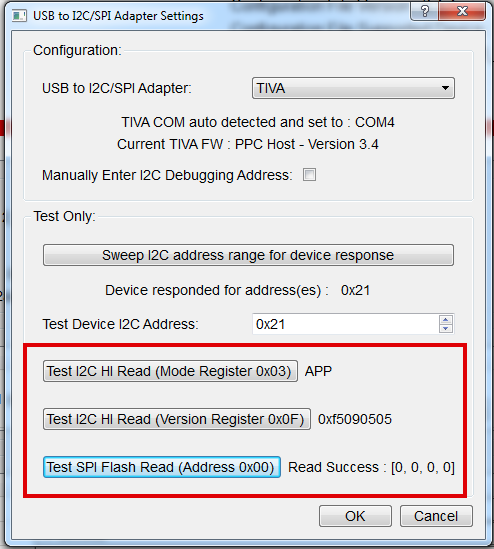
    2. Once loaded, connect your Hardware to your PC and go to Adapter -> Configure I2C/SPI Adapter Settings
    3. In the dialog menu that pops up, change the USB to I2C/SPI Adapter to Aardvark
      1. Click on the Sweep I2C address range for device response button and verify that it finds an address
        1. If it can't find a connection, then there's an issue with the hardware connection
      2. Click on the Test I2C HI Read (Mode Register 0x03) button and verify that the device is in APP mode
      3. Click on the Test I2C HI Read (Version Register 0x0F) button and Test SPI Flash Read (Address 0x00) buttons and verify that they are successful
    4. If everything works across the board, close the USB to I2C/SPI Adapter Settings dialog and return to the main GUI window
    5. Go to Debug -> Debug Mode
    6. Go to the Device 1, port 1 tab
    7. Go to the Commands tab
      1. Under this tab, select HI Firmware Update
      2. Click Read Boot Status
        1. If there are issues with the regions on the device you should see some strangeness here
        2. If you were able to see APP mode in the I2C Adapter window, then the Device Boot Region should point to a working region still on your device
      3. Under the "Load saved Low-region binary file from Computer" section, select Change File and browse to the GUI Installation directoy
        1. This should be the default path that is opened up. If not, under the default installation the path is here:
          1. C:\Program Files\Texas Instruments\TPS65981_2_6_7_8 Application Customization 6.1.1\tps6598x-application-customization
        2. Select the TPS65981_2_6_v0001_12_09.bin file
      4. Now click the Overwrite Backup Region (Unknown)
        1. This will overwrite the backup region on your device (which is most likely invalid) and should fix the "Invalid Region Pointers" issue you were seeing

  • Thanks for the quick reply.  I'm not in APP mode, see the attached pics.  I'm getting garbage back in that field.  Everything else looks good.

    I can't find the HI Firmware Update under the Device 1/port 1/ Commands menu, and I can't find the  "Load saved Low-region binary file from Computer"  menus anywhere in any menu.  Is this because APP mode is corrupt?

    More screens attached that show reads from registers, and the pjt file.  Basically, we want the same configuration as the eval board, but with it configured such that it uses PP_5V switch enabled to power VBUS.  We are not using PP_HV. 

    Thanks again for your help.

    Best,

    Dave.

    Moda Rev6_basic.zip

  • Dave,

    Thanks for the pjt and the pictures. Based on that information it looks like the fundamental issue is that the device is in a bad state. We need to get it into a known good state before we can look at anything else. A known good state will have the device report in APP mode, with the Version showing the Firmware version as 0001.12.09 and the SPI Flash Read return success. It'll look something like this:

    Go ahead and execute the following process to try to recover:

    1. Open the Application Customization Tool
    2. Load Project
      1. Use this attached project: /cfs-file/__key/communityserver-discussions-components-files/138/TPS65982_5F00_DRP_5F00_Host_5F00_Standard_5F00_611.pjt
    3. Binary -> Flash from Current Project
      1. Leave the default regions. Since your device seemingly has corrupt regions, Reading will likely fail
    4. Power Cycle Hardware
    5. Use my previous instructions to read the Mode from the Adapter -> Configure I2C/SPI Adapter Settings menu

    You should now be in APP mode and able to work with your pjt file.

    Some extra notes:

    1. I took a look at your pjt file and everything seemed to be correct. There weren't any issues that I noticed from a cursory glance
    2. You mentioned using Flash Center and an EEPROM. If you're flashing directly with Flash Center:
      1. Make sure you power on your EEPROM in Flash Center this can be done by going to Power Control in Flash Center and applying the 3.3V supply

  • Hi,

    I did as you suggested, same problem.  Am I on the wrong I2C port? 

    I am connected to I2C1.

    thanks,

    Dave.

  • I've done some more testing.  It seems that the TPS65982 configuration tool is not reading the flash correctly. 

    1. I used Aardvark to erase the flash. (This is done with the 65982 not powered, but the flash is)  I then confirmed it was erased and dumped the whole memory to a bin file.

    2. I powered up the system, and did a flash read and saved it to a file with the config tool.  This was done using the same Aardvark adapter/connections (test spi flash read returned "read success" array 0 0 0 0)

    3. I compared the files, the Aardvark dump read was all FF, but the config tool dump was not. So I'm getting SPI read errors.  Is there a way to change the SPI speed on the config tool or further debug this?  Or do I have a schematic error?  Schematic attached.

    TPS65982_Schematic.zip

  • I scoped the SPI signals, and clearly have contention of some sort when using the config tool, but not with the Aardvark flash tool.  So either my schematic is wrong (MOSI/MISO flipped?) or my assumptions on how to connect the config tool are wrong. 

    I have the Aardvark hooked up to the SPI signals as in SLVUAF8C page 39.  I also have the same Aardvark connected to I2C1.

    If I use Aardvark flash tool, I power down the board and just power the EEPROM, and can read/write the flash.

    If I use the same wiring, but with 65982 powered and using the config tool, I have contention on the SPI data pins.  I assumed that the I2C channel would tell the 65982 to release the SPI bus so that the flash could be read.  Appears to be not the case.  Or I my schematic has an error, we intended to wire it as in the EVM schematic on page 29.

    What is the correct way to connect this to use the config tool?

    Thanks a lot,

    Dave.

  • Hi Dave,

    I am assigning this question to one of our hardware experts, as this was found to not be a GUI issue. They will follow up with you tomorrow. 

    Thanks,

    Emma

  • Dave,

    It will be easiest for me to help debug this if you can send me a picture of the SPI EEPROM connection in your schematic.

    If you do not want it sent publicly, then you can send me a friend request and we can converse over private message.

    Regards,

    Chuck

  • Hi Chuck,

    Here you go.

    Thanks,

    Dave.

    TPS65982_Schematic.pdf

  • Dave,

    The connections on your Aardvark to dot match the version that I am used to seeing.  Here a capture off our our TPS65988 EVM.  I had it most on hand.

    Can you make a jumper cable or use 100 mil male to female connectors to re-route your connection to match the one that is shown?

    The grounds are correct, but none of the other connections look right to me.

    I do not believe that there are 2 different Aardvark mappings, so this is most likely the cause of your issue

  • Hi Chuck,

    The Aardvark connections are mapped correctly off the board.  I can use the Aardvark flash tool to read and write the eeprom directly with the same connections, but cannot write to it using the config tool. 

    So something is up with the config tool I think, or the wiring from the eeprom to the 65982.  Does that look correct to you?

    I can also scan the I2C addresses with the config tool and read back status from the 65982. 

    Check back through the other comments on what we have tried so far. 

    Thanks for the quick replies.

    Best,

    Dave.

  • Dave,

    I checked through your schematic and I do not see any hardware reason that you would be seeing contention on the eeprom.  The SPI appears to be connected correctly.

    The I2C port names appear to be different from the Aardvark to the 65982, but because you can communicate with part, I assume that the connection is made off sheet somehow.

    I will spend some more time looking at this today and get back to you.

    Regards,

    Chuck

  • Yes, the I2C port is connected via a jumper to the Aardvark to I2C1 and this works all the time no prob.

    I feel like I'm missing something basic.  The 65982 communicates via SPI to the external eeprom, and this SPI bus is in parallel with the Aardvark when using the config tool.  When the config tool flashes the external eeprom via the Aardvark SPI, is there some mechanism oe pin state that tells the 65982 to release the SPI bus or power down?  When I scope the SPI bus during a config tool eeprom flash attempt, I can see that there is contention on the bus, MISO/MOSI and the clock are corrupt. 

    This is not the case when using the Aardvark flash tool with the 65982 powered off and the eeprom powered.  This works 100% of the time and the signals are clean.

    Thanks a lot Chuck. 

  • Dave,

    That gives me an idea.

    The Aardvark has a jumper inside that will allow you to disable the internal pull-ups.  You may want to try this because if there is a big enough difference in voltage on the Aardvark, this can cause the types of failures that you are seeing.

    I have only seen this on the I2C side in the past, not the SPI side of the Aardvark.

    Regards,

    Chuck

  • Hi Chuck,

    I was able to get another board, this one the SPI signals look fine.  The config tool reports reading and writing to the eeprom as OK, and I confirmed the writes by dumping the EEPROM.  So we are looking good there.

    However, on boot, the 65982 does not even try to read the EEPROM.  I don't see any SPI clock activity.  When I read the Test I2C Hi read mode register, I get garbage back like before.  The chip is not in APP state. 

    Why isn't it trying to read the EEPROMon power up?

    thanks,

    Dave.

  • Hi Dave,

    Chuck is out for the holidays and will follow up with you upon his return in January. Thank you for your patience. 

    Thanks,

    Emma

  • Hi Chuck,

    I hope you had a nice holiday and things are well with you. 

    Do you have any suggestions for us to help diagnose this issue?

    We really need to get this resolved. 

    Thanks a lot,

    Dave.

  • Dave,

    Are you able to read the boot status register to see what it says?

    This should tell us if the part thinks that there is a bad eeprom even though the gui programming works.

    Regards,

    Chuck

  • Hi Chuck,

    Here you go.  I also attached a snapshot.zip file.

    It does seem to be reading junk from the mode register.

      3581.Snapshot.zip

    Thanks,

    Dve.

  • Hi Chuck,

    I have scoped the SPI signals during boot.  It never attempts to read the eeprom.

    1. Have have triple checked the pinout, I'm sure it is correct

    2. I diode tested the clock pin and MISO, they are connected (not an open).

    3. I think it may be stuck in dead battery mode maybe?  I have buspowerz pulled up to 3V3, and have checked that MISO is also 3V3 on power up.  I don't have any 5V connections ( PP_HV and PP_5V are all 0V).  

    What else could cause this to not attempt to read the eeprom?

    Thanks,

    Dave. 

  • Dave,

    Can you send me your schematic in PM so I can look through everything?

    That will protect your IP.

    Regards,

    Chuck

  • I think I have to friend you before I can PM you,

    request sent.  Thanks a lot.

  • Dave,

    I am going to close out this thread because we have transferred to Private Messaging for schematic review.  We can continue our discussion there.