This thread has been locked.

If you have a related question, please click the "Ask a related question" button in the top right corner. The newly created question will be automatically linked to this question.

THVD1451: Confirmation with power consumption of THVD1451 in datasheet

Part Number: THVD1451
Other Parts Discussed in Thread: THVD1410

Hi Team,

Our customer would like to get clarification regarding Fig. 5 (Driver Differential Output Voltage vs Driver Output Current) and Fig. 7 (Driver Output Current vs Supply Voltage) of t the datasheet. This is for the different Driver output current in the graph.

Based from the customer:

He calculated is: 3.3 V supply with a load of 300 Ohms should be a signal current of 10 mA. This fits to figure 5 on page 12 of the datasheet.
With the additional quiescent current of 3 mA, He would expect a total current of 13 mA.


From the same figure (Figure 5), he takes the value of 42 mA for a load of 54 Ohms.
That would result in 45 - 46 mA total.

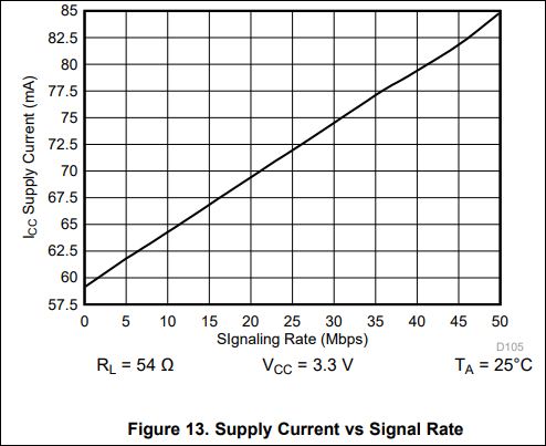
On Figure 7 on page 13 the requested Supply current for 3.3 V supply and 54 Ohm seems to be 59 mA.
This will be 10 to 13 mA more than expected by the customer.

Which of those figures are correct if there's any.

Thanks,

Jonathan

  • Hi Jonathan,

    I think Figure 7 may have been misread. A Supply Voltage of 3.3V on this graph maps to a Driver Output Current of close to 43mA at a load of 54-ohms. This seems more consistent with the expected values from the calculations using Figure 5.

    Figure 7 from THVD1451 datasheet:


    I hope this clarifies. Please let me know if I've misunderstood your question.

    Regards,
    Eric Schott

  • Hello TI-Support, hello Eric Schott,


    Still unsolved Problem.

    I did find this figure 7 at some time before.

    Using this figure I can calculate an effective impedance of 76,7 Ohm. Subtracting the 54 Ohm of the load resistance I get 22,7 Ohm for the internal resistance of the driver.

    When I will use an load resistance of 300 Ohm I will get a signal current of 10 mA.

    So far, so fine. Everything seems to be clear.


    Adding the quiescent supply current (driver and receiver enabled) of 3mA max., I get a total current of 13 mA.

    Also fine.


    But looking at the table of “7.6 Power Dissipation” (on page 9) there is a typical power consumption for 300 ohms load listed of 360 mW.

    Even if I take into mind, that this value is given for V_CC = 5,5 V, it will correspond to an supply current of 65.5 mA.

    And when I scale this power consumption (very rough assumption) linear with the supply voltage (i.e. all internal and external resistances will remain constant), then a supply current of 39.3 mA would be necessary for a supply voltage of 3.3 V.


    And this is my problem.

    Which power consumption ---- in terms of supply current is necessary for a load of 300 Ohms.

    12 mA (which will be fine) or 39,3 mA (which might exceed the capabilities of my power supply).

    And since both data values are calculated on the basis of the datasheet, and only one value can be right, there must be a failure somewhere in these calculations.


    Could you help me, to identify this error.

    Or could you at least provide the correct value for the supply current of this part.

    Operated with 3,3 V supply. Load resistance = 300 Ohms. And driver and receiver both enabled and working with about 30 Mbps.


    Regards

    H.-L Reischmann

  • Hi Reischmann,

    I believe the main discrepancy between the different calculations we've been looking at here is the presence of AC current draw from communication. Figure 7  above shows the current draw of the device when no communication is present (D=Vcc). Because RS-485 uses a symmetrical structure for both logic values, every time there is a state transition on the bus, the driving transceiver will have to charge the bus capacitance from its previous state to its new desired voltage. The more frequently this is done, the more average current is required. This AC component is what is being added to the baseline calculations you've made to end up with the larger current values shown on other graphs and the power calculations on page 9. 

    This AC component is primarily affected by the capacitive load on the bus while the DC component (which you have calculated using figure 7) varies most with the resistive load. To estimate what your total supply current needs are at a higher resistive load, we will need to separate out the AC and DC components.

    First let's look at the specifications for a 54-ohm load from the datasheet. To find the AC component, we can subtract the DC component (43mA found on the figure in my initial reply) from the total supply current needed for this load and voltage at a given data rate. From the figure below, we find this value to be about 58mA. 

    Our resulting AC component is Total_54 - DC_54 = 58mA - 43mA = 15mA. Because this draw is dependant on bus capacitance, it will remain nearly the same as we change the resistive load of the bus. To find our new total at the same data rate, 3.3V, and 300-ohm, we can add your calculated DC component of 13mA to the AC component we just found. Total_300 = DC_300 + AC = 13mA + 15mA = 28mA.

    Please keep in mind that there are estimates that are based on the assumption that many variables remain unchanged. For instance, if the capacitive load of your system differs from what was used to create these specifications, the required AC current component will change. I'll also mention that if your power budget is tight and you don't plan to operate above 500kbps, THVD1410 will have better power characteristics due to less AC current being required at the slower slew rate used in this device variant. 

    Let me know if this makes sense or if you have any questions on this explanation or these estimations.

    Regards,
    Eric Schott

  • Hi Eric,

    thank's for your analysis and your answer, but my problem isn't solved yet. 
    However, it seems to me, that your answer shows, that you might really understand my problem in the next step.

    All the information, which I received from you, could be found in the datasheet, too.
    And I already had found exactly the same information there (fine confirmation).
    But, and that is the point, where my problem starts, and where I believe, that the datasheet includes data, which are in conflict with each other.

    As you stated yourself, there is a difference of supply current in the range of 15 mA, without any explanation for it.

    To repeat my problem:
    And to make it a little bit easier, I will constantly keep the supply voltage at 3.3 V and the load resistor at 54 Ohms.

    1. You are right with the information based on figure 7: 
    With a supply voltage of 3.3 V the driver will deliver a signal current (output) of 43 mA for a load of 54 Ohm.
    I agree, that this will only be valid for a constant output signal without switching and therefore no signal transmission. 
    This is quite understandable, ok. 

    2. You are right with the information based on figure 13: 
    Any signal transmission will charge and discharge the capacitance of the signal wirings for any signal bit transmitted. 
    Therefore, the figure 13 is showing a straight line for the transfer function from signal rate to supply current. This is caused by the fact, that twice the signal switching will request twice the charge needed for changing the voltages on the signal wires. And charge per time = current.
    I.e. The increase of supply current from 10 Mbps to 50 Mbps (which is a difference of 20 mA) is 4 times the increase of supply current from 19 Mbps to 20 Mbps (which is a difference of 5 mA).

    ###: However for a signal switching rate of 0 Mbps (which will be 0 Hz = DC) there is no charging of the signal wires at all.
    Therefore, this supply current should be the same as given for the stationary conditions in figure 7.
    And as you calculated for yourself, there is a difference of about 15 mA (my calculation is similar with the result of 14 mA).

    Wait --- what we are comparing here are two different parameters.
    Figure 7 shows the signal current (output current of the driver), while Figure 13 shows the total supply current of this transceiver.
    And yes, I understand, that there will be a need for some internal current to operate this device. But could this be the explanation for the missing 14 to 15 mA?

    Not to my understanding. On page 10 of your datasheet the quiescent supply current of this unit is documented. And with both, driver and receiver, enabled, the internal current of this device is specified with 3 mA MAX (over all operating temperatures and even for the higher supply voltage of 5 V).

    So, the real difference between the current values given in figure 7 and figure 13 will be reduced by 3 mA. But even then, the explanation for the residual 11 mA is still missing.


    I believe that the total supply current should be based on three parts.
    a) the quiescent current, which is needed tor the internal operation of this unit,
    b) the DC part of the signal current, which is determined by the load resistor,       and
    c) the AC part of the signal current, which is needed to charge and discharge the capacitance of the signal wires, and which will be proportional to the signal transmitting frequency.

    Where is the additional forth contribution to the current consumption of this unit?
    And this is the point, which I still don’t understand.


    Regards,
    Hans-Ludwig Reischmann

    P.S. Your recommendation of the THVD1410 is fine (and it is included in the identical datasheet). But, since my planned signaling frequency is in the range of 15 Mbps, my design will need the faster transceiver THVD1451.


  • Hi Hans-Ludwig,

    I believe I understand the discrepancy you're pointing out here. It appears that the DC cases do not line up between Figures 7 and 13. I believe this is because the specified behavior on graph 13 changes as it approaches the DC case. It's likely that the samples used to generate this graph were only taken in the linear region of this behavior and extrapolated to fill to 0Mbps. Therefore, this graph should primarily be used to estimate current consumption at operational data rates and not in DC cases. For DC cases, Figure 7 will provide more accurate estimates. 

    For a more in depth analysis of this, we can see how the current consumption changes as data rates decrease by comparing Figures 13 and 19. Figure 19 with a range from 0kbps to 500kbps shows a near linear relationship with a slope of about 28uA/kbps (estimated between 100kbps to 450kbps). Figure 13 wich ranges from 0Mbps to 50Mbps also shows a near linear relationship, but with a much smaller slope of about 0.5uA/kbps (estimated between 5Mbps to 45Mbps). This shows that the relationship between data rate and supply current is not entirely linear through these ranges, especially close to the DC case. Electrically, we would also expect this. Fundamentally, the parasitic capacitances of the system along with the impedance of the driver circuit form a low-pass filter. Because we know that the current-frequency relationship in such circuits is not linear, we can expect similar behavior here. 

    In summary, you point out a valid point: that the DC data point on Figure 13 is inaccurate, likely due to the extrapolation used to create the figure. However, the data point at 5Mbps is a measured value, so all other data points should be representative of expected behavior. There is no (significant) fourth contribution to supply current apart from what you have listed above. For estimating the DC case, I would recommend use of Figure 7 because this behavior was specifically measured at the given conditions. 

    Regards,
    Eric Schott

  • Hi Eric,


    thank you for your helpful answer.
    I will follow your advice and design my power supply in the way that it should be able to deliver the supply current according to figure 13. If the supply current really needed will be slightly lower (due to shorter signal wires and therefore reduced capacity) the design will be on the save side.

    However, considering your first information, that the slope of current consumption relative to signal rate is mainly caused by the current necessary to change the voltage (and therefore also the charge) on the signal wires, I tried to calculate the corresponding capacity (extrapolating the signaling rate to 1 bit per second => current responds to 1 times charging the wiring capacity). At a load of 54 Ohms and a signal current of 44 mA the signal voltage will be 2,37 V, and the voltage for charging/discharging the wires will be twice this value = 5.75 V.

    Based on figure 13 with 0.5 µA/kbps = 500 pA/bps, with a voltage change of 5.75 V the corresponding capacity would be 87 pF.

    Based on figure 19 with 28 µA/kbps = 28 nA/bps, with a voltage change of 5.75 V the corresponding capacity would be 4.9 nF.

    Looking for typical vales for load capacitances I found 1 twisted wire (don’t know if this is typical) with a capacity of 43 nF/km.

    It seems that some parts of the discrepancy between figure 13 and figure 19 could be explained by different measurement conditions, with the slower part THVD1410 of figure19 is used for longer distances with cable length of 100 m (300 ft) and more – see figure 33 which shows the relation between cable length and data rate, while the faster part THVD1451 of figure 13 is used for shorter cables (< 1m).
    And, even if the measurement conditions for both parts are identical (the table 7.8 for the switching characteristics lists a load capacity of 50 pF for both drivers) the reduced slew rate of THVD1410 might be achieved by some additional internal capacities, which would result in an increased slope of supply current versus signal rate.

    If this assumptions would be right, than there might be another error in your datasheet, since the faster part might have an increased quiescent supply current versus the slower part. However, this will be only an academically question, since I will work - as advised by you - trying to find a design solution able to deliver the current in accordance to figure13.

    Regards,
    Hans-Ludwig Reischmann

  • Hi Hans-Ludwig,

    You are indeed very perceptive and I applaud your dedication to these calculations. I have definitely learned in my career that there's always another source of error that has not been accounted for, hazards of working with electromagnetic properties in the real world. 

    To address your latest (academic) point, I believe one of the sources of difference we see between THVD1410's and THVD1451's consumption slopes is indeed their slew rate. Because a faster edge contains more high frequency contents, this energy will more readily be lost through capacitive parasitics than slower edges. This is the same reason that faster edges tend to cause more electromagnetic radiation; this energy is emitted to the environment instead of being used to charge the signal line. I'm not sure if this is the main contributor to the differences we see in these graphs, but it is definitely significant and is one of the advantages to using a slower-rated device, even when operating at the same data rate. 

    As this energy difference is only seen when the device is transition, it would be considered an active consumption and not quintessential, which would focus on the consumption when so transitions are occuring. 

    Regards,
    Eric Schott

  • Hi Eric,

    Thank you for for helpful information.

    I did learn a lot.

    Kind regards,

    H.-L Reischmann