This thread has been locked.

If you have a related question, please click the "Ask a related question" button in the top right corner. The newly created question will be automatically linked to this question.

DS90UB940-Q1: Can I Connect Multiple FPD-LINK Serializer Sources To Same Deserializer Sink By A Shared-Pin Connector

Part Number: DS90UB940-Q1


Hello

We Have A Problem Due To Mechanical Design. Our Mechanical Design Ask Use Connectors As Lesser As Possible. So I Think Maybe We Can Interconnect Different FPD-LINK Serializer To One Deserializer. Following Is My Plan:

1. Suppose I Can Use CAN Bus To Control / Through Host Controller On Display Side To Use I2C Interfacing With Deserializer To  Stop Transmissions From Serializer According To The Functionality Of FPD-LINK.

2. Depending On My Use Case Each Time I Can Select Either Of Them To Transfer Wanted Video Just Need Re-Config The Framerate / Clock And Re-sync.

3. Presume The Total Millisecond Time Spent Upon Re-Configuration Would Not Influence Human Sense.

4. In My Case 2 Pairs Of Deserializer Use Same Pins For DP / DN / SGND

Hope My Plan Can Reduce Uses Of Connectors / Circuits Of Connectors. 

  • Hi Bright,

    Just want to make sure I understand the use case correctly, I assume you will only use one serializer at a time right? 

    Are the four serializers on the same PCB?

    Best Regards,

    Charley Cai

  • Hi Charley

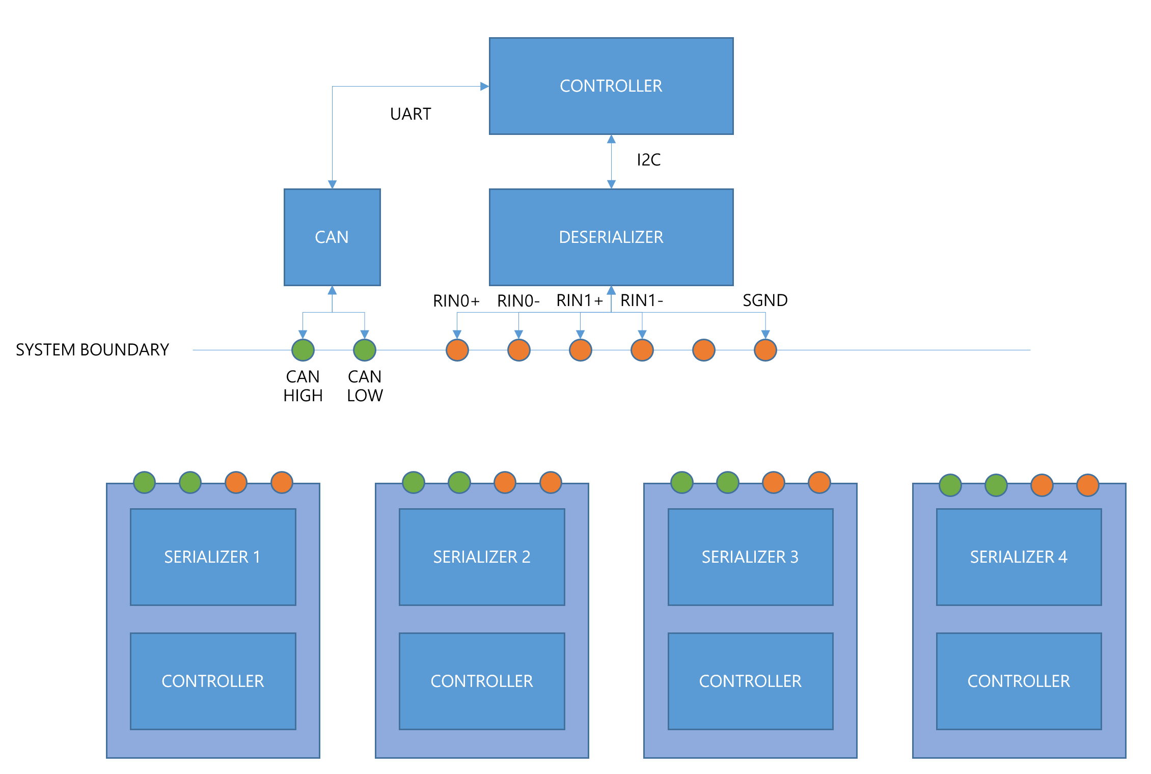
    Here Is Only One Deserializer With One 6-Circuit Connector As You See In The Diagram And Four Serializers Are Separate Each Other In Standalone PCB.  My Purpose Is Make The Four Serializer All Together Into The Connector Then To The Deserializer.

    Bright

  • Hi Bright,

    I dont think this would be possible with 6 circuit connector. Each serializer would need at least 1pair of wire so the 6 circuit connector doesn't have enough wires to support all four serializers. 

    If it does, you would need a high speed switch at the deseriazer side to two the input because the deserialzier will always needs to take data from RIN0+/- pins and may need RIN1+/- for dual FPD-Link mode.

    Best Regards,

    Charley Cai

  • Charley

    Looks That You Don't Really Understand My Question. As I Mentioned I Want To Use Shared Pins Of A Small Connector Due To Poor Space Of Mechanical Design. So I Put My Diagram And Explain How Am I Planning To Do.

    First

    Each Time Only Allow One Link Transmission

    Second

    Resync / Reconfig By Deserializer Side

    Third

    I2C / CAN Bus Control

  • Bright,

    Yes, I am not getting how you plan to share the pins between four serializers if they are on different PCBs.

    Could you explain in a different way? 

    I am assuming you will need at least two output pins for each serialzier.

    If you have a good way to share/fit these into one connector, the rest should work. 

    One issue is that if you plan to switch source while the display is on, you will likely see a flicker happening on screen.

    Best Regards,

    Charley Cai

  • CHARLEY

    I Don't Know Why You Don't Understand. Here's Diagram With Flow Descriptions. As I Said Through I2C Control I Can Command Either Of Deserializer To Stop Transmission / Disconnect From The Link And I Also Can Re-Sync / Re-Config The Setting For Different Input Video. If I Cannot Through I2C To Control Serializer Then The Other Way Is CANBUS. They Are All Different Hardware Devices Designed With Controller.

    As Diagram Post Above When I Want Video Application Transmitted From Serializer 1 I Can Stop Transmission From One Of Serializer Connected In Shared Pins Or Just Disconnect It. Let's Assume Serializer 1 Use Pins In Common With Serializer 2 And Serializer 3 With Serializer 4. If I Want Input Video Of Serializer 2 What Should I To Do Is Disconnect Serializer 1 / Command It To Stop Transmission. I Post My Question For Possible Electrical Issues. For Example Electrical Interference. If Here Is Only Likely A Flicker I Can Decide A Delay Time To Wait For Flicker Gone. So It Is Not A Big Problem. For My Case Deserializer Will Connect To A Processor Then Display For Video Overlay And Rotation. If Deserializer Side Cannot Use I2C To Command Serializer Then Plan B Is CANBUS. Each Of Serializers Designed With Controllers Along With CANBus Transceiver. I Can Through Can Bus To Communicate With Controllers And Use Controllers To Control Serializers.

    Bright

  • Hi Bright,

    This will work if you are going to disconnect the unused serializers. 

    Best Regards,

    Charley Cai

  • Hello Charley

    Let's Make A Conclusion That If I Through Controller Of Deserializer To Stop Transmissions From The Unwanted Video Input From Serializer I Can Release Channel For The Wanted In The Same Pins Right? For Example If Serializer 1 And Serializer 2 Use Same RIN+ / RIN- To Deserializer I Can Send Command To Stop Transmission From Serializer.

    Bright 

  • Hi Bright,

    Yes, since you have CAN and I2C bus control, you can disable serializer outputs to stop transmission.

    Best Regards,

    Charley Cai