This thread has been locked.

If you have a related question, please click the "Ask a related question" button in the top right corner. The newly created question will be automatically linked to this question.

TUSB8041: TUSB8041 USB2.0 Signal Integrity Simulation

Part Number: TUSB8041

Hello:

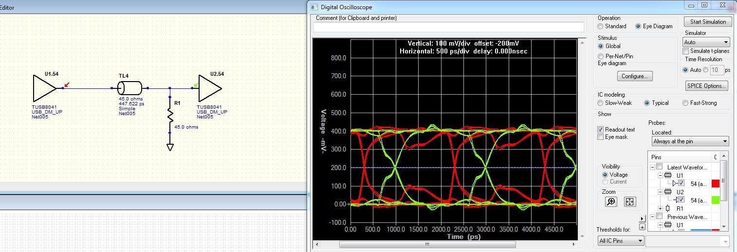
I'm trying to do a USB 2.0 signal integrity simulation. In order to do that I connected directly the USB_DM_UP U1 transmitter pin to U2 USB_DM_UP receiver pin. I know that it's a 90 ohms differential bus, but in order to simplify the design I've used only one 45ohm single ended line, connected through a 45Ohm transmission line, as it can be seen in the next figure:

It can be seen in green the received signal, it's reasonable good signal. However the signal in U1 (in red) is really awful, I don't know whether is normal or is due to some error in the simulation.

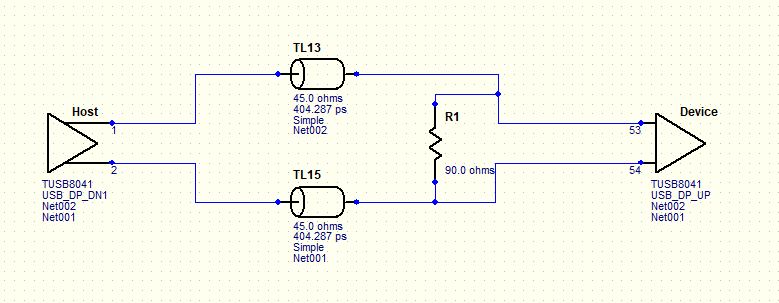
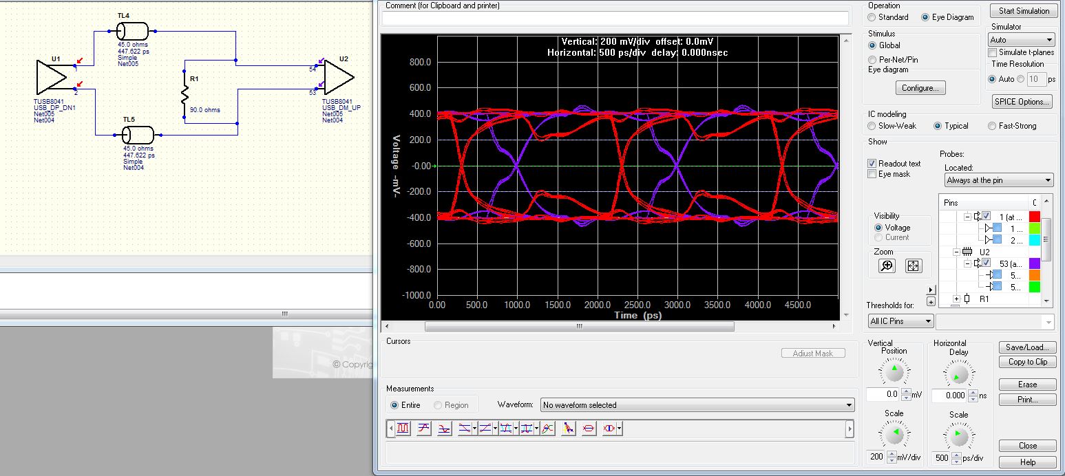
In order to improve the signal in U1 transmitter side I've added an 45ohm resistor in order to suppress the reflection, however this resistor is not used in the real circuit, so the simulation is like that:

In that case the signal quality in both sides has improved. So I will like to know whether the simulation is right and how the quality of the signal can be improved without using the 45ohm resistors, maybe using some internal ODT in the TUSB8041 or any other simulation setup.

Thanks in advance for your time.

  • Hi Sam,

    Can you reattach the images, they didn't come through.

    What is the end application?

    Thanks,

    JMMN

  • Hello JMMN:

    Thanks for your answer, I am planning to connect the TUSB8041 to a microcontroller to use it as a Hub.

    I send you attached the images, which were missed in my last post.

    In the first one the USB transmitter signal (in red) it's connected to a receiver signal (in green), the signal in the transmitter side is awful:

    In order to improve the signal I have added a 45 ohms in the receiver side (However in the real world this resistor is not used) and the signal improves in both sides:

    I have also performed simulations with differential driver and 90Ohms differential transmission line and the results are similar. So my question, is there anything wrong in this simulation?.

    Thanks for your time.

  • Hi Sam,

    I would recommend setting it up as differential simulation and adding a 90 ohm differential resistor connection at the inputs.  I recall this was needed for the HyperLynx sims for some reason, but not on the other tools.  Obviously, it would not be required in the actual implementation.

    Regards,

    JMMN

  • Hello:

    Thanks for your comments, I have set up the differential simulation adding an external 90ohms and the shape of the received wave (in purple) is good. As you can see below:

    So it's a little confusing to have to include an external resistor if it is actually included in the TUSB8041 receiver , some supplier included both models with an without odt (On Die Termination resistor). It will be a good idea to include both in the available models or at least have the resistor always included in the IBIS model.

    Regards ,

  • Hi Sam,

    I agree it if very confusing for HyperLynx users.  I will feedback that to the modeling team.

    Regards,

    JMMN