This thread has been locked.

If you have a related question, please click the "Ask a related question" button in the top right corner. The newly created question will be automatically linked to this question.

DS90UB954-Q1: DS90UB95 output rate setting problem

Part Number: DS90UB954-Q1

Hi,Ti

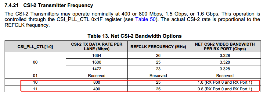
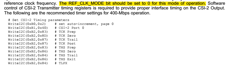
When I set the sensor data input of DS90UB953 to 400bps,The output of the DS90UB954 set to 400bps cannot display the image,I set DS90UB954 to the output of 800bps to display the image normally.

What is the reason and what parts need to be set up?

  • Dominic

    pls make sure the design follows up the 953/954 design request, and check your issue step by step. it could be 953's input issue, or 954 output setting issue or the on-board SOC issue. anyway you should check it clearly.

    1. what is the input signals to 953

    a. CSI2_CLK signal, pls provide detailed clock freq.

    b. how man data lanes are used?

    2. how to set 954's output?

    a. how to set the 400Mbps? pls follow up the d/s request (timing should be updated since it is not 800Mbps, this is described in d/s

    b. how many data lanes are set?

    3. question: what error is reported when set 954 at 400Mbps? is it SOC issue followed with 954?

    Steven

  • Hi,Steven

    1. what is the input signals to 953

    a. CSI2_CLK signal, pls provide detailed clock freq.

    =>200Mhz

    b. how man data lanes are used?

    =>2 lane

    2. how to set 954's output?

    a. how to set the 400Mbps? pls follow up the d/s request (timing should be updated since it is not 800Mbps, this is described in d/s

    =>set the rigister that the datasheet describes  

    Datasheet says that the sending timing parameters of CSI 2 need to be set to different rates. How should these parameters be set?

    By the way, are there any other reference documents besides the datasheet?

    b. how many data lanes are set?

    =>2 lanes 

  • Hi,Steven

    Pick up an email

    3.question: what error is reported when set 954 at 400Mbps? is it SOC issue followed with 954?

    Let me describe the phenomenon again: our company adopts IMX327,2 lane MIPI, 400Mbps/ LABE, input to 953, and transmit to 954 by STP.
     
    When the output data rate of 954 mipi is set to 400Mbps, the CPU cannot receive the 954 code stream and produce the image.
    Set it to 800Mbps to create the picture normally.
     
    We don't see any error on the 954 or 953, the only chip we have access to is the I2C interface, you can point to the registers to see if it's working or not.
     
    Please check the following register values of 954 and 953 when 954 is set to 400Mbps and 800Mbps

    I cannot add the attachment of the register value. Could you please send me your email address?

  • Hi,

    1. if the csi2 data from 953 csi2 port is 400Mbps/lane *2lanes, the ub954 can be set as 400Mbps/lane *2lanes with 25M ref. clock and +/-50ppm. pls make sure the imx327 output clock, it is better if you can provide the test plot

    2. for 400M setting inside 954, pls ignore the REF_CLK_MODE. You just set the CSI2 PLL to select 400Mbps and fine tune the dphy timing parameters. 

    3. any error is reported in the soc which follows up the 954?

    Regards,

    Steven


  • Hi,Steven

    1. if the csi2 data from 953 csi2 port is 400Mbps/lane *2lanes, the ub954 can be set as 400Mbps/lane *2lanes with 25M ref. clock and +/-50ppm. pls make sure the imx327 output clock, it is better if you can provide the test plot

    =》The IMX327 output clock is 222Mhz

    2. for 400M setting inside 954, pls ignore the REF_CLK_MODE. You just set the CSI2 PLL to select 400Mbps and fine tune the dphy timing parameters.

    =》what should the REF_CLK_MODE be set if setting 400Mbps? which charter of the datasheet  does the dphy timing parameters should refer to when set 400Mbp、800Mbps or other rate?

    3. any error is reported in the soc which follows up the 954?

    =>no error report in SOC.Only media control has been reporting errors, indicating no code stream.

    The test waveform is as follows.

  • in summary:

    1. the sensor output csi2 rate should be <=400Mbps/lane * 2lanes if you want to enable 954's 400Mbps/lane *2lanes mode

    2. to set 954's 400Mbps mode, you refer to reg. 0x1F to change the rate also fine tune the timing which  is pasted by you as example in d/s.

    regarsd,

    Steven 

  • Hi,Steven

    1. the sensor output csi2 rate should be <=400Mbps/lane * 2lanes if you want to enable 954's 400Mbps/lane *2lanes mode

    =》so,with our design where the  Sensor output cis-2 rate 445Mbps/lane*2, should we enable 4's 800Mbps/lane *2lanes mode?

    2. to set 954's 400Mbps mode, you refer to reg. 0x1F to change the rate also fine tune the timing which  is pasted by you as example in d/s.

    =》how to set the 800Mps timing ?the d/s only show the timing with 400Mbps


    Best Regards

  • hi,

    1, yes. in your case, 954 can't be set as 400Mbps/lane x2lanes

    2. for 800Mbps, you don't need any setting on the timing, the default is designed for 800Mbps.

    regarsd,

    Steven