This thread has been locked.

If you have a related question, please click the "Ask a related question" button in the top right corner. The newly created question will be automatically linked to this question.

TCAN1043-Q1: Wake up solution

Part Number: TCAN1043-Q1

Dear team,

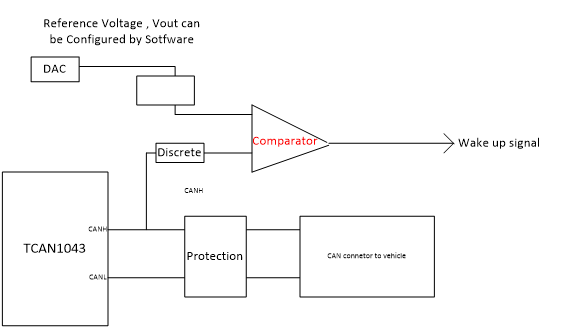
My customer has a new demand about the wakeup function. It is required that on CANH or CANL, once there is a DC voltage exceeding a certain threshold, the system should wake up, and the threshold needs to be programmed. Currently we want to use below block diagram to achieve this function, but we are not sure if it is ok? Do you have better ideas?

Thanks & Best Regards,

Sherry

  • Hello Sherry,

    Does the wake up signal control the TCAN1043-Q1, or is that wake up signal driving another system not shown?

    The TCAN1043-Q1 has Local Wake Up (LWU) and bus wake up pattern (WUP) functionality, so I will assume that the wake up signal shown in your diagram is being used to control an external system not shown.

    One of my concerns is making sure that there are no asymmetry issues that arise from tapping into one wire of the CAN bus. It would be prudent to make sure that your discrete system feeding into the comparator is high-impedance, and that the routing does not create a lengthy stub. If this is a very small system, then I imagine it should not have too large of an impact on the signal.

    Regarding CANH vs CANL, note that in standby mode, the CANH and CANL signals both drop to low voltage, rather than recessive voltage. This means that standby mode would potentially trip any voltage minimum threshold being used if monitoring CANL.

    That being said, I'm not completely sure how this customer intends to implement this solution, so it might not be an issue. It's worth examining.

    It is for this reason that I would expect CANH to be the better selection to monitor for this application.

    Without changing the characteristics of the CAN bus, one would expect to see a consistent bus output dominant voltage (VO(D)) from this device during operation. Is there another device on the bus that would provide the DC voltage? Is this reference voltage expected to be higher than the VO(D) of the CANH signal? Please let me know if I misunderstand the implementation shown in your diagram.

    Best,

    Danny

  • Hi Danny,

    Thanks for your reply!

    The function that my customer wants to achieve is that when our device and the system is in sleep mode , once there is a DC voltage exceeds the threshold on the CANH lane, the system should wake up and realize there is a fault pulse or fault voltage on the CANH lane. At the time our device can't wake up the system because our device only wakes up when receiving fixed format pulses, so we need to add external circuit to achieve this function. The source of the fault DC voltage may be various, for example CANH lane short to voltage when 1043 is in sleep mode.

    Could you please help check whether we have any better idea?

    Thanks & Best Regards,

    Sherry

  • Sherry,

    The only inherent detection mechanism the TCAN1043-Q1 has is bus fault detection where voltage shorts on CANH and CANL can be reported by the nFAULT pin. Unfortunately, this function is not available in sleep mode, so it's not useful in this particular case. An external comparison will be necessary, but as Danny pointed out in his first reply, since the solution would be connected to one of the CAN bus lines, there's an issue of asymmetry if the circuit isn't properly designed. Please make sure that if the customer does go this route, that the conductor lengths, and impedance don't cause significant changes to the CAN bus voltages.

    Regards,

  • Hi Eric,

    Got it! Thank you!

    Best Regards,

    Sherry