This thread has been locked.

If you have a related question, please click the "Ask a related question" button in the top right corner. The newly created question will be automatically linked to this question.

SN65DSI86: Hardware Design for SN65DSI86

Part Number: SN65DSI86
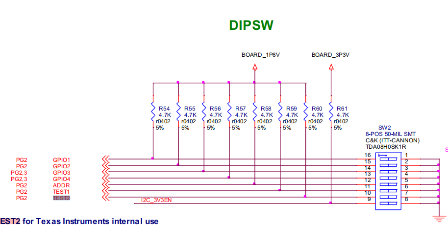
Other Parts Discussed in Thread: TXS0102, TEST2

Hello Support,

i have already designed one hardware for SN65DSI86 but i failed to run it due to not able to i2c communicate with chip.

so now,

I'm want to design one new hardware board for SN65DSI86.

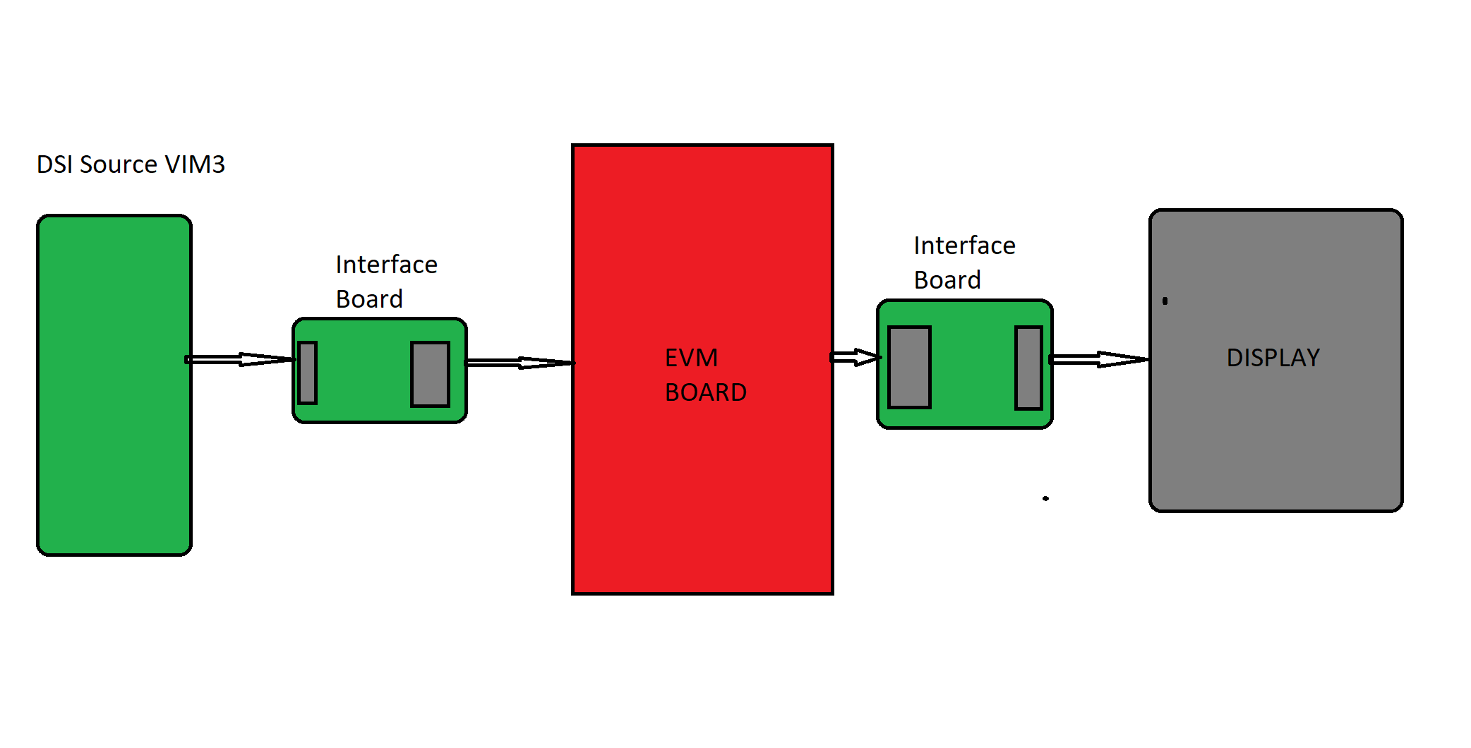
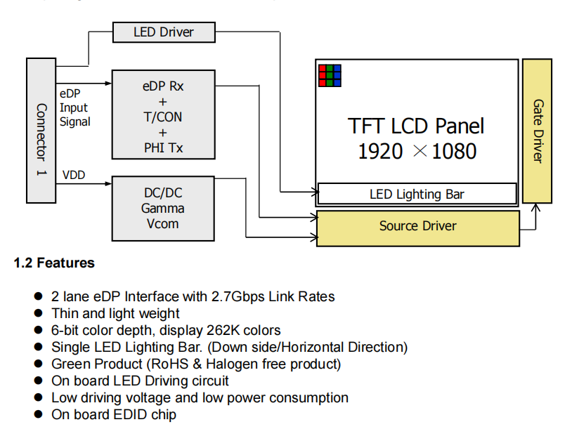
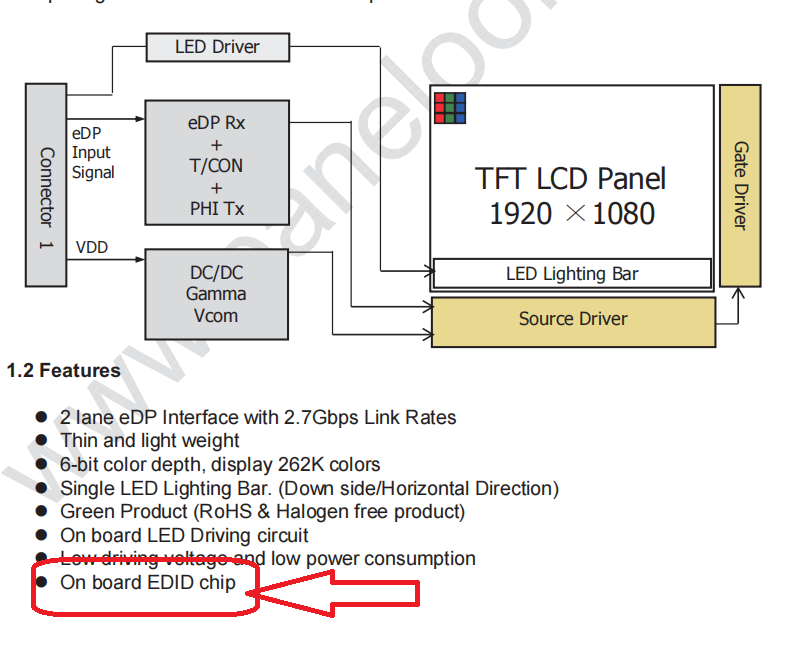
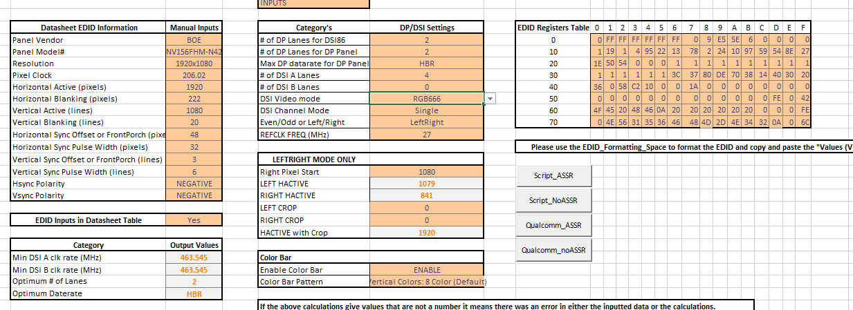
to drive NV156FHM-N42(1920x1080)LCD DISPLAY using KHADAS VIM3 MINI COMPUTER BOARD.

I have attached necessary details with for this application

like

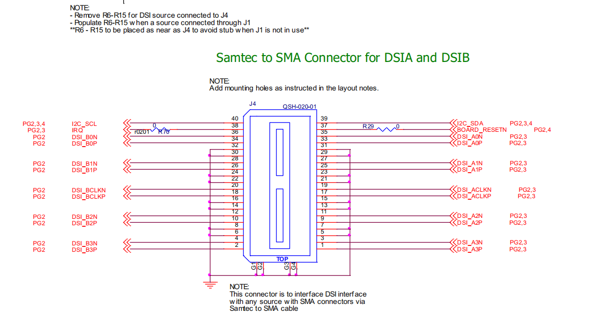
VIM3 board MIPI port pinout
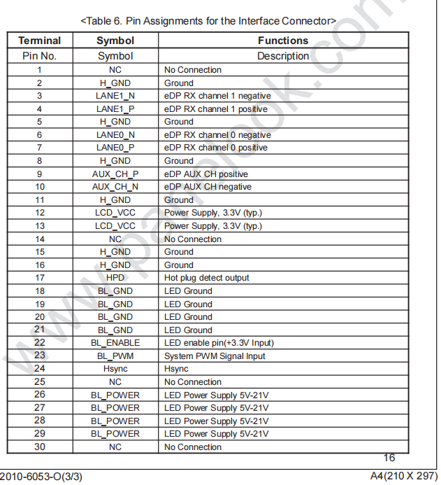
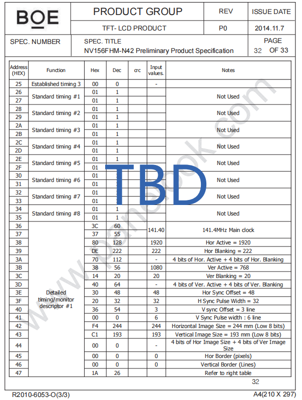
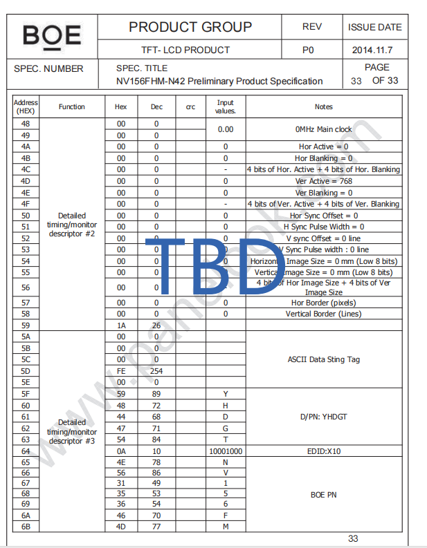
LCD display pinout

Datasheets for same

So,please help me to design hardware board

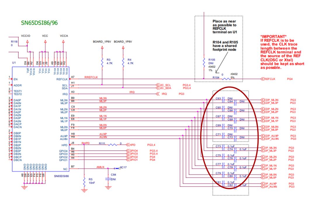
i have already followed reference design last time but still i got failed to run

so this time i don't want to fail with design

so please help to get design board for the same

Thank you very much.

App Deatails.pdfLCD SCREEN NV156FHM-N42.pdfProcessor VIM3_V12_Schematic.pdfOld_DSI86_HardwareDesign_Schematic.pdf

  • Hi,

    Are you still trying to solve the I2C bus issue or are you running into a new issue with the DSI86 design?

    If it is still the I2C bus issue, can you please remove the R10 and R11 since the TXS0102 has internal 10k pullup. Can you also add 10k pullup on the MIPI_SCL_3V3 and MIPI_SDA_3V3 to see if it helps?

    If the I2C communication still fails, can you probe both sides of the TXS0102 using a scope?

    Thanks
    David

  • Hello david,

    I'm going to buy one evm board for same so what other things i will be needed along with this board for testing and debug purpose.

    i don't know what kind of accessories will be come with EVM and what i have buy from my end.
    please help me

    thanks

  • Hi,

    You would need an external 5V supply.

    I would also recommend getting an external I2C controller such as the Total Phase Aardvark.

    If you only want to output the color bar, the EVM should work as is. If you want to output the DSI data, then you need to build an interface board between your DSI source and the DSI86 EVM.

    Thanks
    David

  • Hello David,

    The DSI source(VIM 3) and display both have same FFC/FPC connector FH12-30S-0.5SH.

    but EVM has no such kind of connector so do i have to build 2 boards to operate EVM

    like,from DSI source to EVM and from EVM to eDP Display.

    and Do i have to order EVM board cables as well  it comes along with EVM board.

    and if i don't want to buy Total Phase Aardvark then is it possible to configure DSI86 using other way

    like MCU i2c communication or from DSI source.

  • Hi,

    Your block diagram is correct.

    On the output side, I am thinking you can use the standard DP connector and connect to a regular DP display, this will save you the cost and time of building the second interface board.

    Thanks

    David

  • Hello David,
    Thanks

    And if i don't want to buy Total Phase Aardvark then is it possible to configure DSI86 using other way

    like MCU i2c communication or DSI source(VIM3)

  • Hi,

    Yes, you can use the MCU I2C or DSI source to control the DSI86. Since you had an issue with the I2C bus, I just thought the Aardvark I2C controller offers another option of controlling the DSI86.

    Thanks

    David

  • Thanks david
    let me do work for the same.give me few time
    i will update you soon

  • hello david,

    i need little help to design interface card

    because i have FH12-30S-0.5SH connector with both vim3 board and lcd display

    so i need to make connections from board to evm and evm to display so

    how to make connections

    i have attached all 4 connector pinouts

  • Hi,

    On the DSI side, you want to follow the lane order and connect MIPI_DSI_D0P/N to DSI_A0P/N ,etc.

    On the eDP side, this looks to be a standard eDP 30pin interface, you can use this design as a reference.

    8407.dsi86_edp_30pin_RevA.zip

    Thanks

    David

  • Thansk David,
    i will share schematic once i complete .

  • hello david

    do i have to connect this pins comes from VIM processor board connector

    and if yes then where?

    here it's evm connector

  • Hello david,
    please check schematic
    i have implemented two in one interface card single card for both side interface

    so please check my connections

    evm_interface.pdf

  • Hello david,
    please check schematic
    i have implemented two in one interface card single card for both side interface

    so please check my connections

    6813.evm_interface.pdf

  • Hi,

    Pin 38 on the DSI side Samtec connector is IRQ, not LCD_EN. Otherwise the schematic looks ok to me.

    Thanks

    David

  • Hi david,

    Thanks and i have received EVM board and given interface card for printing

    i have scanned EVM address using arduino and it's able to scan address 0x2D

    now how i can configure it?

    and what kind of configuration and needed

    and how the DSI tuner is useful?how to use it?

    here is my LCD display specifications

    Here is the datasheet

    NV156FHM-N42-BOE.pdf

    one more question once i configure evm using extrnal host mcu like arduino then do i need any change in VIM3 processor board(DSI source)or it will work. i mean display will work with board.

    Thanks.

  • Hi, 

    The DSI86 is not being supported by the DSI tuner. Instead, you can use this spreadsheet to generate the DSI86 registers programming value based on the panel's EDID information. Please see this e2e link for the spreadsheet: 

    I would recommend to enable the color bar first. The color bar is generated internally and can be used to verify the eDP interface first. Once the color bar is working, you can then turn it off and focus on the DSI interface. The VIM3 processor board should work with the DSI86 as long as it is meeting the timing and protocol as required by the DSI86.

    Thanks

    David

  • Thanks David,

    I will update you soon.

  • Hello David,

    I'm not able figureout spreedsheet

    i tried to understand README but still not getting ecject idea what to do next?

    i'm not confident with my current knowledge what to do next ,how to use spreedsheet

    what to configure ?

    can you please help me.

    thanks

  • Hi,

    There are two ways to input the data into the spreadsheet to generate the DSI86 register programming value. 

    If you have the panel EDID information, you can choose to input the panel's EDID information into the EDID_Formatting_Space worksheet. You can then copy and paste the information from the EDID_Formatting_Space worksheet into the EDID Registers Table in the Main_Input_Page worksheet. C22 in this case needs to be set to 'No'.

    If you don't have the panel EDID information, you can choose to input the panel data in row C10 to C20 in the Main_Input_Page worksheet. C22 in this case needs to be set to 'Yes'.

    Row F7 to F15 need to be set depending on your design. For example, in your design, you are use channel A 4 lanes. So F11 needs to be set to '0' and F13 needs to be set to 'single'.

    Since you are not using Qualcomm processor, you need 'Script_ASSR'  if the panel supports ASSR or 'Script_NoASSR' if the panel does not support ASSR. When you click on the  'Script_ASSR'  or 'Script_NoASSR', the spreadsheet will generate a text file under Window's folder 'Documents'.

    Thanks

    David

  • Hello david
    Thanks a lot

    here in the datasheet they mention that it has onboard EDID chip. what does it mean?

    and here is my panel EDID information.

  • Hi,

    EDID information specifies the panel's vendor, supported video resolution, pixel clock, etc.

    Since you have the panel EDID information, you can manually input the panel's EDID information into the EDID_Formatting_Space worksheet. You can then copy and paste the information from the EDID_Formatting_Space worksheet into the EDID Registers Table in the Main_Input_Page worksheet. C22 in this case needs to be set to 'No', to generate the DSI86 register programming value.

    Thanks

    David

  • Hello david,
    i have configured EVM board using arduino microcontroller as a i2c host.

    now do i need to write drivers for VIM3 linux board or i can run it directly?

    like  interface evm with VIM3 board and Display without driver because i already configured EVM board .

    Thanks

  • Hi,

    If you configured EVM using the Arduino microcontroller as a I2C host, are you able to successfully configure the DSI86 registers?

    Can you please enable the DSI86 color bar and verify it is working? This will isolate the DSI and verify the eDP side is working.

    Once the color bar is working, you can then disable the color bar and focus on the DSI interface. Do you need the driver in order to send the DSI commands to the DSI86?

    Thanks

    David

  • Hello David,
    how yo verify the EVM is configured perfectly because i can write registers using i2c host.
    how to enable color bar

    we try to enable colorbar but not sure

    and after that i have interfaced lcd but there is no color bar on display.

    we have enabled color bar as per spreadsheet.

    please check my generated ASSR script.

    <aardvark> 
    <configure i2c=1 spi=1 gpio=0 tpower=1 pullups=0/> 
    <i2c_bitrate khz=100/> 
    
    ======REFCLK Frequency  ====== 
    <i2c_write addr=0x2D count=1 radix=16> 0A 6 </i2c_write>/> 
    
    ======DSI Mode  ====== 
    <i2c_write addr=0x2D count=1 radix=16> 10 26 </i2c_write>/> 
    
    ======DSIA Clock  ====== 
    <i2c_write addr=0x2D count=1 radix=16> 12 3F </i2c_write>/> 
    
    ======DSIB Clock  ====== 
    <i2c_write addr=0x2D count=1 radix=16> 13 3F </i2c_write>/> 
    
    ======DP Datarate  ====== 
    <i2c_write addr=0x2D count=1 radix=16> 94 20 </i2c_write>/> 
    
    ======Enable PLL  ====== 
    <i2c_write addr=0x2D count=1 radix=16> 0D 1 </i2c_write> <sleep ms=10/> 
    
    ======Enable ASSR in Panel  ====== 
    <i2c_write addr=0x2D count=1 radix=16> 64 1 </i2c_write>/> 
    <i2c_write addr=0x2D count=5 radix=16> 74 0 1 0A 1 81 </i2c_write> <sleep ms=10/>
    
    ======Enable enhanced frame and ASSR in DSI86  ====== 
    <i2c_write addr=0x2D count=1 radix=16> 5A 5 </i2c_write>/> 
    
    ======Number of DP lanes  ====== 
    <i2c_write addr=0x2D count=1 radix=16> 93 20 </i2c_write>/> 
    
    ======Start Semi-Auto Link Training  ====== 
    <i2c_write addr=0x2D count=1 radix=16> 96 0A </i2c_write> <sleep ms=20/> 
    
    ======CHA Active Line Length  ====== 
    <i2c_write addr=0x2D count=2 radix=16> 20 80 07 </i2c_write>/> 
    
    ======CHB Active Line Length  ====== 
    <i2c_write addr=0x2D count=2 radix=16> 22 0 0 </i2c_write>/> 
    
    ======Vertical Active Size   ====== 
    <i2c_write addr=0x2D count=2 radix=16> 24 38 04 </i2c_write>/> 
    
    ======Horizontal Pulse Width   ====== 
    <i2c_write addr=0x2D count=2 radix=16> 2C 20 00 </i2c_write>/> 
    
    ======Vertical Pulse Width   ====== 
    <i2c_write addr=0x2D count=2 radix=16> 30 06 00 </i2c_write>/> 
    
    ======HBP   ====== 
    <i2c_write addr=0x2D count=1 radix=16> 34 8E </i2c_write>/> 
    
    ======VBP   ====== 
    <i2c_write addr=0x2D count=1 radix=16> 36 0B </i2c_write>/> 
    
    ===== HFP  ====== 
    <i2c_write addr=0x2D count=1 radix=16> 38 30 </i2c_write>/> 
    
    ===== VFP  ====== 
    <i2c_write addr=0x2D count=1 radix=16> 3A 03 </i2c_write>/> 
    
    ===== DP-18BPP Disable  ====== 
    <i2c_write addr=0x2D count=1 radix=16> 5B 0 </i2c_write>/> 
    
    ===== Color Bar Enable  ====== 
    <i2c_write addr=0x2D count=1 radix=16> 3C 12 </i2c_write>/> 
    
    ===== Enhanced Frame, ASSR, and Vstream Enable  ====== 
    <i2c_write addr=0x2D count=1 radix=16> 5A 0D </i2c_write>/> 
    
    </aardvark> 


    thanks.

    and what is ASSR and non ASSR?

    how i can check for my application?

  • Hi david,
    i tried with many configuration with given spreadsheet

    also verified the data is correctly written

    but there is no colorbar on display.

    so i'm not getting the idea where is the issue.

    Thanks

  • Hi,

    ASSR is part of the eDP spec, some eDP panels support ASSR while other panels do not support ASSR. By default, the DSI86 is enabled to support ASSR. But you can disable the ASSR by the following steps.

    1. Pull TEST2 pin to 1.8V thru a 1k to 10k resistor.
    2. Write 0x07 to register 0xFF. This will select Page 7.
    3. Write 0x01 to register 0x16. This will make ASSR_CONTROL to be read/write.
    4. Write 0x00 to register 0xFF. This will select Page 0.
    5. Write 0 to bits 1:0 at register 0x5A. This will change from ASSR to Standard DP.

    Can you also dump out register 0xF0 to 0xF8 and in particular register 0xF8 to see if there are any errors reported by this particular register?

    Thanks

    David

  • Hello david,

    i didn't get you for this
    Can you also dump out register 0xF0 to 0xF8 and in particular register 0xF8 to see if there are any errors reported by this particular register?

    and as per EVM schematic
    TEST2 is already pulled up with 4.7K resistor

    thanks

  • Hi,

    With TEST2 pin already pulled up, please write these commands to disable the DSI86 ASSR

    1. Write 0x07 to register 0xFF. This will select Page 7.
    2. Write 0x01 to register 0x16. This will make ASSR_CONTROL to be read/write.
    3. Write 0x00 to register 0xFF. This will select Page 0.
    4. Write 0 to bits 1:0 at register 0x5A. This will change from ASSR to Standard DP

    The status registers located at offsets 0xF0 thru 0xF8 can provide valuable information on failures which can result in black or flickering panel. Please refer to this e2e FAQ for more information on the registers 0xF0 to 0xF8. From reading these registers, I want to understand the reason of black panel.

    Thanks

    David

  • Hello david,
    i'm not aware of following terms in spreadsheet
    i didn't find in datasheets and so
    i dont' know how to select please guide me.

    > Datasheet EDID Information<
    Hsync Polarity
    Vsync Polarity

    >Category<
    Min DSI A clk rate (MHz)
    Min DSI B clk rate (MHz)
    Optimum # of Lanes
    Optimum Daterate


    >Category's<
    Even/Odd or Left/Right
    REFCLK FREQ (MHz)

    >Color Bar<
    Color Bar Pattern


    here is my configurations

    ---------------------------------------------------------------------------------------

    and 
    here is configuration read from EVM and F0to F8 resistors

    *************************************** read configuration 
    16  > 1
    A    >86
    10  >A6
    12  >5C
    13  >5C
    94  >80
    D   >1
    5A  >4
    93  >20
    96  >0
    20  >C0
    21  >3
    22  >C0
    23  >3
    24  >38
    25  >4
    2C  >20
    2D  >0
    30  >6
    31  >0
    34  >8E
    36  >B
    38  >30
    3A  >3
    5B  >0
    3C  >10
    *************************************** read F0to F8
    F0  >36
    F1  >80
    F2  >44
    F3  >36
    F4  >36
    F5  >0
    F6  >36
    F7  >0
    F8  >36
    ***************************************

  • Hi,

    > Datasheet EDID Information<
    Hsync Polarity
    Vsync Polarity

    *** This comes the panel datasheet. Since you are input the EDID directly into the spreadsheet, this doesn't matter.

    >Category<
    Min DSI A clk rate (MHz)
    Min DSI B clk rate (MHz)
    Optimum # of Lanes
    Optimum Daterate

    *** This is calculated based on the input information, you don't need to fill it out


    >Category's<
    Even/Odd or Left/Right

    *** This comes the panel datasheet and only used if using both DSI A and B channel. Since you are only using A channel, this does not apply in this case.

    REFCLK FREQ (MHz)

    *** This is based on the DSI86 EVM which is 27MHz crystal clock.

    >Color Bar<

    Color Bar Pattern

    *** Please refer to the DSI86 datasheet. The color bar pattern selects different pattern to be outputted on the LCD panel.

    Looking at your Excel spreadsheet.

    • The EDID information does not match 100% with the EDID information provided in the panel's datasheet
    • If you are inputting the EDID information, you should select 'NO' in the 'EDID Inputs in Datasheet Table' field.

    Looking at register 0xF8, it shows link training failure, and both the CLK and EQ training failed. Did you change the capacitor location on the EVM as shown below?

    Thanks

    David

  • Hello David,
    i have changed cpacitor position

    but still not getting color bar

    the registers now

    3C>13
    FF>0
    16>0
    FF>0
    A>86
    10>26
    12>3F
    13>3F
    94>20
    D>1
    5A>4
    93>20
    96>0
    20>80
    21>7
    22>0
    23>0
    24>38
    25>4
    2C>20
    2D>0
    30>6
    31>0
    34>8E
    36>B
    38>30
    3A>3
    5B>0
    3C>13

    F0>36
    F1>36
    F2>36
    F3>36
    F4>36
    F5>36
    F6>36
    F7>36
    F8>36

  • Hi,

    I don't understand how the DSI86 status registers can all return with the same value of 0x36.

    I wrote a script file of 600x800 color bar resolution with 2 eDP lane at 1.62G. Can you please see if it works? My expectation is it will work. If not, please double check the DSI86 hardware connection and read out the entire DSI86 registers.

    2DP_4DSI_RBR_800x600_Color_Bar.zip

    Thanks

    David

  • Hello David,
    i tried with upper script as well but it is also not working
    still getting dark screen no colorbar
    i also verified connections and it seems fine.

    now what could be the issue.
    thanks

  • Hi,

    Can you please dump out the DSI86 registers with the 600x800 color bar script?

    Thanks

    David

  • Hi david,
    i'm not getting any solution
    i stuck here

    thanks

  • Hi,

    I sent you a private message, would you please check?

    Thanks

    David

  • Hi, Please see my private response. Thanks David