A related question is a question created from another question. When the related question is created, it will be automatically linked to the original question.
If you have a related question, please click the "Ask a related question" button in the top right corner. The newly created question will be automatically linked to this question.
UA9638: Max sinking current and maximum dissipation of the output NPN sinking transistor
What's the use case the customer is concerned? The maximum sinking current is around the Ios (150mA). Assume 30Ohm impedance, the dissipation of the NPN could be around 30*0.15*0.15=0.675W.
BTW, if the customer is interested, the latest TI RS-485 are listed in this post.
Thank you very much for supporting this thread and let me greet you a happy new year!
Upon sharing your answer with our customer, he some additional questions below:
TIA/EIA-422 defined max cable length for RS422 at 4900ft, which implies wire to wire approximate capacitance in range of 80 nF. If the driver withstands only 150 mA sinking current - then how does it even withstand discharging the circuit in its max length? For sake of an example - if circuit is just 140 ft long, which is reasonable - then 24 AWG wire is 3.5 Ohms and approximately 2.2 nF capacitance. This creates roughly between half and one amp of discharge impulse at peak which can be measured using fast current probe. This means that the chip is capable of working with much higher currents than 150mA sinking current - otherwise your chips wouldn't be capable of working with RS422 at all and they would fail. The customer question here is about repeatable peak transistor current at say duty cycle of 1% to 5%. What would that be?
Let me know your comment or if you have any questions with the customer, please let me know.
It's a good question. Your estimate about the capacitance is correct. However if we look closely, the cable can be segmented into many small RLC pieces.
Therefore the capacitor are not lumped into one value. In general, if the propagation delay on the cable is longer than 6 times of the rise time of the signal, the cable should be treated as transmission line. If you're interested, this app note has many good information about transmission and signal quality.
Also FYI, some lab data is captured in this app note with different data rate and distance. Although it's tested with different transceiver, you can get the idea of long distance communication.
I asked about Repetitive Peak Current value of the NPN sinking transistor of UA9638 and it is my primary concern.
I am using the driver with multiple different load circuits - as there are different cables used, different lengths and different terminations - which makes it difficult to analyze. My circuits are conducting quadrature pulses on a variety of industrial controls. My application is automation, not transmission.
For example - one application is a driver for a Yaskawa AC Drive utilizing 5.5V supply and 300 Ohms termination for a complimentary signal pair. This means the driver outputs loop together over a twisted pair of 24AWG conductors. Other systems utilize 68 Ohms single termination to ground. Another application is a handwheel with 120 Ohms termination for a complimentary signal pair. I also have other, more complex termination circuits.
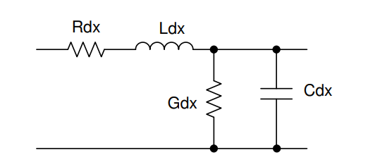
I see an elevated failure rate of these chips and I am not sure what's causing it. I noticed the discharge current that varies widely from product to product. That current can be 0.6A and higher. Assuming that the failures are related to capacitive discharging I want to fix the problem by applying fix to all the devices at once. If I knew the maximum allowed discharge current of the chip - let's call that Repetitive Peak Current value - it would be easier for me to select a protective resistor. My protective resistor would be added in series with wire resistance Rdx presented in the figure above.
So for a sake of an example if we assume Gdx to be 120 Ohms, Cdx to be 2.2 nF and Ldx=0 and Rdx=0 - I'd like to select a protective resistor value that would protect the chip from discharging overcurrent in the NPN sinking transistor.
Can you specifically point out how the discharge current varies from product to product? From my experience, most RS-485 transceivers have similar driving capability per RS-485 standard (1.5V with 54Ohm). Also can you elaborate how the failure is caused by capacitive discharging (I've seen more caused by ESD events)? Generally speaking the failure due to the over current is a reliability issue, in which the outcome is described in probability.
Andrew is currently having issues responding easily in e2e so I will respond on his behalf.
According to Andrew below:
" I'd like to reply that a 140 feet cable has a different discharge than that of 10 feet cable on our products. I also can't elaborate on discharge failure, because - as I said - I don't know. I suspect. I need help. Thanks."
In many RS-485 applications, the long cables are applied (sometimes over 1km). From my experience, the signal traveling on the long cables usually create quality issues rather than reliability issue. Is it possible to submit the failure parts to TI quality team for failure analysis? Here is the information page.
BTW, what're the reasons UA9638 was chosen? What's the key specifications in the system? Maybe you can test newly released RS-485 like THVD1550 or THVD250 that come with better protection or higher fault voltage.
Here's the updated response I receive from the customer just to review all:
The customer has the uA9638C driver in production - not the other parts. The part fails due to unknown conditions. They did extensive testing over the last 2 weeks that confirmed the designs - and based on that they suspect that the transient voltage could be the prevailing failure reason, but not 100% sure.
They would like to ask for the repeatable peak sinking current of the NPN sinking transistor in the uA9638C driver.
To be honest, this question is hard to answer. How do you define the 'repeatable' like frequency, intermit? What is more difficult is to characterize reliability of a transistor, which involves some conditions such as gate voltage. The third point is that the failure could occur in the ESD cells not the transistors. I think practically the customer still uses 150mA as the limit. From my experience, it's more often to see the device get damaged if the transient pin voltage exceeds the abs max.