This thread has been locked.

If you have a related question, please click the "Ask a related question" button in the top right corner. The newly created question will be automatically linked to this question.

TCAN4551-Q1: Schematic review

Part Number: TCAN4551-Q1

Hi  Bu:

Happy new year.

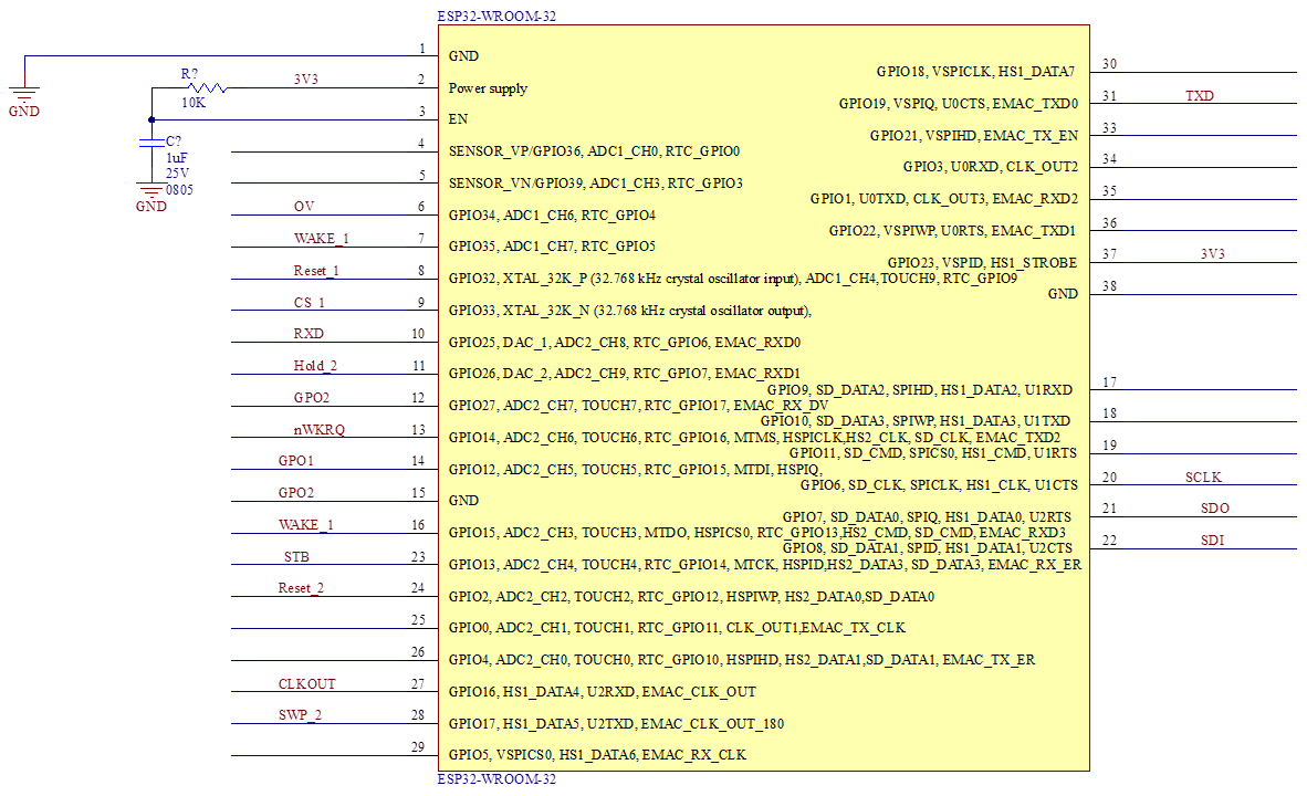
I need your help to review the schematic I attached, the application is a OTA system in automotive

  • Jason,

    Thanks for bringing this review to E2E, and happy to see more customers using our SPI-to-CAN device!

    Some points of feedback:

    • FLTR, VIO, and VCCOUT are all correctly decoupled. Make sure all of these are close to their respective pins in the layout.
    • WAKE is tied to VSUP, which means the local wake feature won't be available in this solution. Is that intended?
    • nINT needs an external pull-up, it is an open-drain output unless the device is in test mode.
    • The termination resistors are both 1.6k, adding up to 3.2k. This is okay as long as this is not one of the end nodes on the CAN bus. If this is an end node, the termination resistors both need to be 60 ohms, adding to 120 ohms total.
    • The SPLIT termination capacitor typically ranges from 4.7nF to 100nF, with the most common value being 4.7nF. 47nF is perfectly fine, I'm just verifying the intention to use this value.
    • All rest of the CAN bus components look sufficient.

    Please let me know if you have any other questions.

    Regards,