Part Number: DP83867IR
Hello,
I'm connecting to a DP83867IR with a Kintex 7 FPGA. All of the bootstrap resistors are giving me the desired values on the registers using the recommended resistor values in Table 4 of the datasheet, with the exception of the internal test mode register, controlled by bootstrapping pin RX_DV (pin 53 on the QFN part).
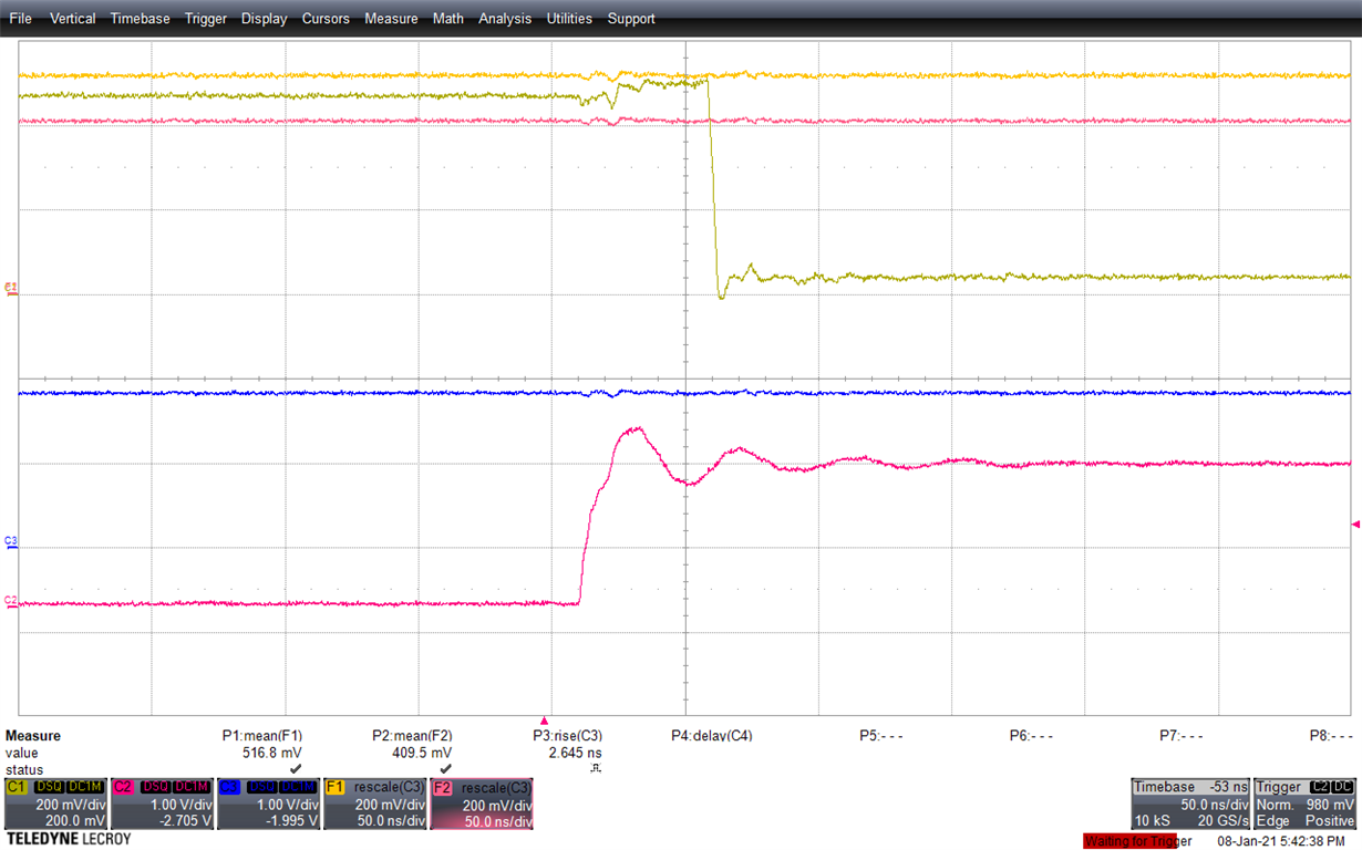
I'm running this design to exclusively use gigabit Ethernet, so I need to set Auto-Negotiation to '0' and internal test mode to '0', which means I should be operating in Mode 3. Here is a trace of the bootstrap pin, reset signal and 1.8 Volt power supply.
- C1: RX_DV pin 53
- C2: Reset_N pin 59
- C3: VDDIO power supply (set to 1.8 Volts) pins 57, 41 and 23
- F1 = VDDIO x 0.284
- F2 = VDDIO x 0.225
I can access the MDIO interface to confirm the strapped values.
- I'm reading Autonegotion enable is set to '1' by reading bit 12 of BMCR, register address 0x0000.
- I'm reading Autonegotion enable is also strapped to '0' (autonegotiation enabled) by reading bit 7 of STRAP_STS1, register address 0x006E.
- I'm reading internal test mode is set to '1' (test mode enabled) by reading bit 7 of CFG4, register address 0x0031
- I'm unaware of any register bits that can return the strap configuration of the internal test mode
Assuming the strapped voltage levels are read in at the rising edge of the RST_N signal, The PHY should be operating in Mode 3, according to the osscilloscope trace.
Do you have any idea why the PHY is starting up in the internal test mode?
Many thanks!


