Part Number: DP83867IR
Hello,
I'm continuing on from the thread about the overshoot on the VDDA2P5 power supply on the DP83867, which I created on the 25th of November. That thread is now locked.
I confirm that there is no power supply connected on the magnetic Jack.
A Tusonix 4701-001LF was used to connect the output of the LDO to the 2.5 Volt Analogue Power Supply. I also tried replacing this Pi-Filter with a wire link, but the fault persisted.
I managed to get the board working by connecting a 2.5 Volt digital power supply from a DC-DC converter to the VDDA2P5 power supply. The DC-DC converter was starting up in 630 us, which is about eight times the ramp time of the linear regulator that was previously being used. Does the VDDA2P5 drive any kind of inductive load in the Ethernet magnetics where a fast ramp time could cause inductive kickback?
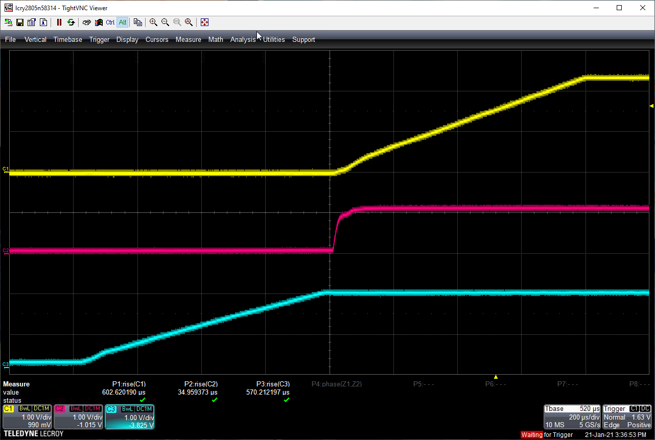
Regarding the power supply ramp times, here is an oscilloscope trace of the power on sequence:
- Channel 1 (yellow) : VDDA2P5
- Channel 2 (red) : VDDIO (Set to 1.8 Volts)
- Channel 3 (Blue) : VDD1P1
The 1.1 Volt power supply is provided by the same LDO regulator component that was used to power the VDDA2P5 (you can see from the measurements that it rises in ~40us). Just to be clear that the 2.5 Volt trace in this oscilloscope shot is now sourced from the digital DC-DC converter power supply on the board, rather than the 2.5 Volt analogue linear regulator.
Are there any requirements on the ramp times for these power supplies which I may have violated?
Many thanks!