This thread has been locked.

If you have a related question, please click the "Ask a related question" button in the top right corner. The newly created question will be automatically linked to this question.

DP83867IR: auto negotiation issue

Part Number: DP83867IR
Other Parts Discussed in Thread: MSP-EXP430F5529LP

Hi,

I am using DP83867IRPAPT in a 100 base TX application.

The strap configurated is RX_D0=1; RX_D2=1; RX_D4=3; RX_D5=1; RX_D6=3;RX_D7=1;RX_CTRL=3;CRS=2;LED1=3;LED0=1. 

MDC is not used.

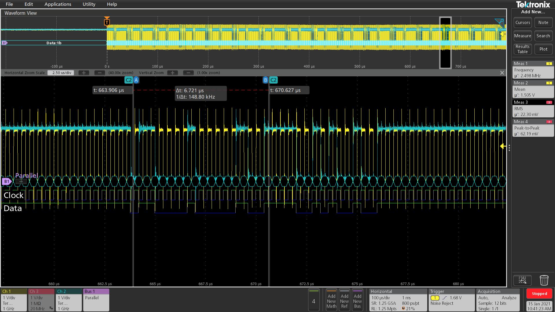
When RJ45 is not connected, I am always able to see the Fast Link Pulses on TD_P_A and TD_M_A pins.

Sometimes I see the FLP on TD_P_B and TD_M_B pins as well. But after powering off and then powering on the board,  FLP sometimes disappears from TD_P_B and TD_M_B (sometimes FLP is still there). 

This uncertainty causes issue, the network sometimes can be detected while sometimes cannot. 

P.S. I am not using an crossover network cable. 

Can someone please help? Thanks in advance.

  • Is there a reason you are not using MDC? Have you followed the steps using the troubleshoot guide? 

    Thanks

    Cecilia

  • I have gone through the PDF and still didn't find any clue.

    I didn't use MDC is because I'd like to simplify the design as strap configuration is good enough in most cases.

    Today I modified the strap to configure PHY address and enabled MDC communication in FPGA.

    Device: DP83867IRPAPT

    Supply: VDDIO=VDDA2P5=2.5V; VDD1P1=1.1V; VDDA1P8=floating

    Strap: RX_D0=3; RX_D2=1; RX_D4=3; RX_D5=1; RX_D6=3;RX_D7=1;RX_CTRL=3;CRS=2;LED1=3;LED0=1. 

    I captured the two cases (TD_P_B   FLP presence and absence) with oscilloscope. Below is the decode from MDIO and MDC waveform:

    Case1: FLP present on TD_P_A  but not on TD_P_B  

    01 10 00010 00000 Z0 0011 0001 0000 0000
    01 10 00010 00100 z0 0000 0001 1110 0001
    01 01 00010 00100 10 0000 0001 0000 0001
    01 01 00010 01001 10 0000 0100 0000 0000
    01 01 00010 00000 10 0011 0011 0000 0000
    01 10 00010 00000 z0 0011 0001 0000 0000
    01 10 00010 00100 z0 0000 0001 0000 0001
    01 10 00010 01001 z0 0000 0100 0000 0000
    01 10 00010 00001 z0 0111 1001 0100 1001
    01 10 00010 00001 z0 0111 1001 0100 1001
    01 10 00010 00001 z0 0111 1001 0100 1001 (repeating...)

    Case2: FLP present on TD_P_A  and TD_P_B 

    01 10 00010 00000 Z0 0011 0001 0000 0000
    01 10 00010 00100 z0 0000 0001 1110 0001
    01 01 00010 00100 10 0000 0001 0000 0001
    01 01 00010 01001 10 0000 0100 0000 0000
    01 01 00010 00000 10 0011 0011 0000 0000
    01 10 00010 00000 z0 0011 0001 0000 0000
    01 10 00010 00100 z0 0000 0001 0000 0001
    01 10 00010 01001 z0 0000 0100 0000 0000
    01 10 00010 00001 z0 0111 1001 0100 1001
    01 10 00010 00001 z0 0111 1001 0100 1001
    01 10 00010 00001 z0 0111 1001 0100 1001 (repeating...)
    ...
    01 10 00010 00001 z0 0111 1001 0110 1101 (after I plugged in straight RJ45 cable)

    In both cases, the registers captured shows the same information. However, the IC behaves differently in the two cases.

    Case 1 and Case 2 are randomly happening. e.g. a system reboot might transform system from Case 1 to Case 2.

    Any possible reasons for the issue? Any advice on other items I can measure further? 

    Below is the sample MDC waveform.

    Thank you very much in advance. 

  • I will need to review these waveforms further but have you confirmed whether you are using auto-mdix and if setting it to forced mdi or mdix has helped?

  • Hi,

    According to oscilloscope measurement of  the strap voltage, it is confirmed the strap setup for "AMDIX Disable" is "3" which means AMDIX is enabled.

    Today I did another experiment: keep all the condition same except I enabled "Force MDI/X" (by setting strap=3). After modifying the strap, it is found that TD_P_B and TD_M_B always have FLP while TD_P_A and TD_M_B doesn't often show FLP. It means "Force MDI/X" strap is able to make some difference.

    I ordered an USB2MDIO board (MSP-EXP430F5529LP) from TI so that we can access PHY registers easier (comparing to using FPGA). Hopefully it could arrive this week.

    Any signal I can measure before the USB2MDIO arrives?

  • Hi,

    I think that is good progress that you are seeing the differences occur when enabling force. Do you know if you have strapped to forced MDI or forced MDIX? Another thing to check is if you have a cross cable and see if that changes with your strapped modes

  • Hi Cecilia,

    Thanks for your suggestions for solving the problem.

    The root cause is addressed and problem has been resolved.

    Today when I am using oscilloscope to measure the strap voltage,  it is found that the voltage is not as same as my past record. Then I measured the VCCIO, de-soldered and measured the strap resistors, finding they are in a normal range. 

    Then I reviewed the system to look for the possible reason. After debugging, it is found that the reason is in the FPGA. The straps are multi purpose signal, as they are FPGA input as well. In FPGA, the pull-down resistor (R_fpga) is enabled by default and therefore pulling down the strap voltage. What is more, the R_fpga is changing from time to time. That is why sometimes the FLP presents and sometimes doesn't. The one affecting the AMIX is RX_D6.

    The problem is resolved after I disabled the pull-down resistor in FPGA.

    Your help is highly appreciated.

    best regards,

    Li