Part Number: TUSB1210EVM
Other Parts Discussed in Thread: TUSB1210,
currently, it tries to operate [controller + usb 2.0 camera] .
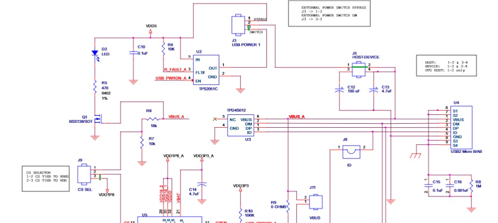
The states of each jumper are as follows.
J1 [open]
J2 [open]
J3 [2-3]
J5 [1-2]
J6[1-2]
J7[open]
J8[open]
J9[1-2]
J11[open]
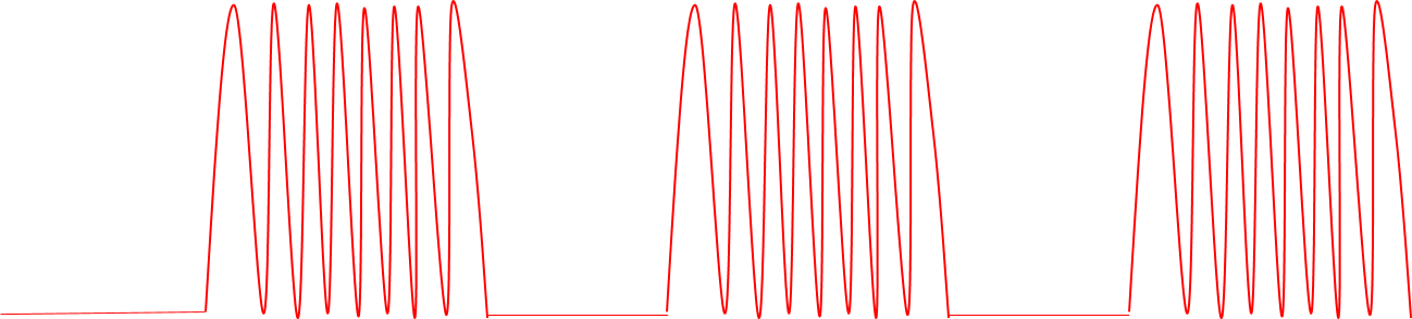
When configured in this way, the USB protocol analyzer recognizes it as LS communication.
How do I configure jumper pins for HS communication?
And when J9 is set to [2-3], the clock is not output, and I am curious what the functions of J8 and J11 are.
Please understand that the context is strange because I used Google Translator.