This thread has been locked.

If you have a related question, please click the "Ask a related question" button in the top right corner. The newly created question will be automatically linked to this question.

AM26C32: Single-ended interface with AM26C32

Part Number: AM26C32

Hi,

As known, AM26C32 device is a quadruple differential line receiver for balanced or unbalanced digital data transmission.

Now customer requires compatibility with single-ended input. And we have two ways to meet that.

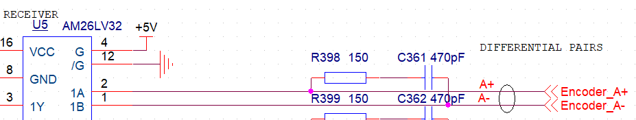
1、Input A+ connects to single-ended signal, leave pin A- floating.

2、Input A+ connects to single-ended signal, connect the A- through a resistor divider with Vcc.

Obviously, the second method is more reasonable relatively.

But by test, both methods are feasible and the first one performs better.

TI don't provide Pspice model, I cannot do a functional simulation.

So,refer to the functional block diagram below in the datasheet, I do functional simulation with pspice.

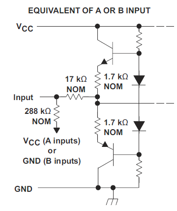
The result is puzzling that very different from expectations.

My question :

1、Please help to explain the phenomenon.And which method should be used.

2、For single-ended signals, are there any anti-interference measures?

3、Before, I use a RC filter between A+ and A-,the single-ended signal is greatly affected by RC. Does it have to be removed?

Thanks.

  • In theory, using a differential receiver as a comparator should work. What exactly do you mean with "performs better"? What are the resistor divider values?

    1. The internal resistors bias a floating input to a certain voltage. The resistor values are nominal and have quite large tolerances, so there isn't much of a guarantee. What voltage do you measure at this pin? (And what are the input signal's voltage levels, 0 V and 5 V?)

    2. The 288 kΩ resistor is quite weak, and can easily pick up noise.

    3. This is not a RC filter but AC termination. For single-ended signals, the termination (if you want it at all) should be against ground, or another low-impedance voltage. In no case can you use the same termination as for a differential signal.

  • Thanks for reply.

    ''Perform better'' means that with high input frequency,the output signal is not distorted.

    1、The voltage is 2.35V. The voltage level is 0V and 5V.

  • Eric,

    Echoing Clemens' point, I think method two 'adding resistor divider' is preferred due to the internal weak bias. However depending on the data rate and distance, the signal integrity needs to be taken into account. Here is a blog discussing the termination and reflection.

    e2e.ti.com/.../rs-485-basics-when-termination-is-necessary-and-how-to-do-it-properly

    If you share some waveforms of the two methods, I can help take a look.

    Regards,

    Hao