This thread has been locked.

If you have a related question, please click the "Ask a related question" button in the top right corner. The newly created question will be automatically linked to this question.

TPS65987DDJ: TPS65987DDJ I2C interface

Part Number: TPS65987DDJ
Other Parts Discussed in Thread: TPS65987, TPS65987D,

Hello everyone,

I hope you are all doing well.

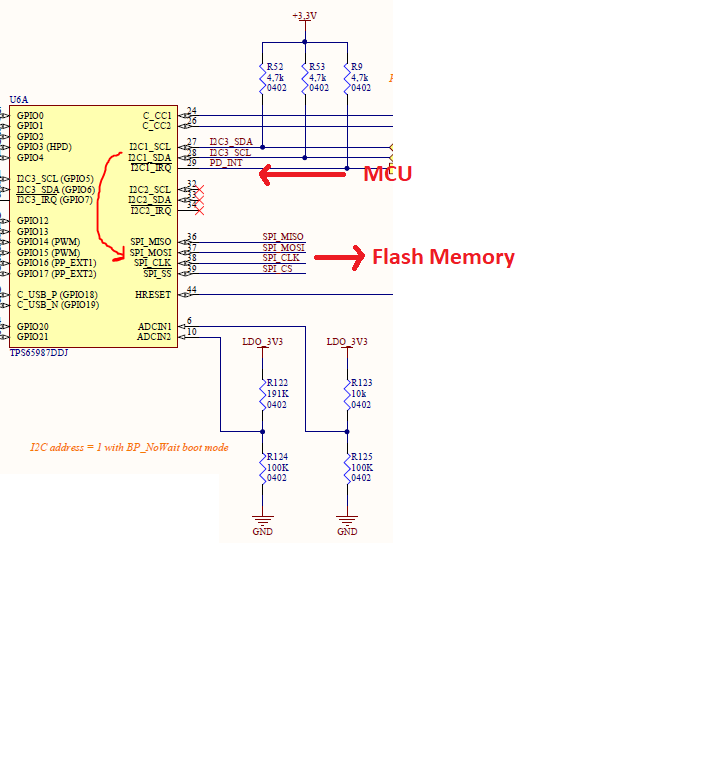
So, I have used a TPS65987 on a custom board. Unfortunately, I've wired only the I2C1 interface with the MCU, and the SPI interface only with the Flash, no external access :( I know, big mistake, should have at least put some test points.

I thought we would be able to configure the flash by talking with the TPS via it's I2C1 interface, but apparently not.

As we couldn't configure the TPS, we have bought the EVM board to see what we should do. Apprently the memory is flashed directely via SPI (through FTDI converter), the actual reading and writing in the different registers is done via I2C2 and not I2C1.

I mean we tried to not use the Flash memory, just configure the TPS directely via I2C, but unfortunately for the moment we cannot do anything with the I2C1 interface.

But from what I've understood in the datasheet is that I2C1 is the actual configuration interface, and can be master or slave.

So can anyone please tell me why I2C1, even on the EVM board, is not usable in this case? Is it a matter of slave/master configuration (as I2C2 is only slave)? Did I misunderstand the datasheet? Is there anything we can do to configure the TPS with only I2C1 interface and a Flash memory linked only to the TPS?

PS: I am not an embedded system engineer as the current  lack of details might show (they are very busy so I'm investigating) , but If  you need any information I can provide it quickly.

Thank you for your help!

Best regards,

  • Hello,

    Are you trying to flash the TPS65987D through I2C? This is possible, and I can provide you a document with information on this via private message. I do not think it will be possible to connect I2C to a flash device as flash devices use SPI communication. 

    Thanks,

    Emma

  • Hello Emma,

    Thank you for your answer.

    Yes we do want to flash the TPS65987D through I2C. It would be very helpful if there is a doument that details the process (We researched several documents available on the website, I am not sure we have this one though).

    Will it be possible through I2C1 interface though? That seems to be a problem, as in we can read registers but not write through this interface.

    For the Flash memory, I might not have explained properly: I thought it would be possible to send commands from the MCU to the TPS65987 through I2C, instructing it to transmit a configuration to the flash memory through its SPI interface.

    Please send me the document. Thank you again for your help.

    Best regards,

  • Hi Mariem, 

    I sent the document to you. If you have the TPS65987D connected directly to flash, you should be able to flash the device through the flash memory using an I2C to SPI programmer, like an Aardvark adapter/flash center. 

    What GUI are you using? I notice here you are using the TPS65987DDJ, which is recommended only for PC notebook/TBT designs. The TPS65987DDH is recommended for all other applications.

    Thanks,

    Emma

  • Hello Emma,

    Thank you for the document.

    So, there are 2 issues, I'll put 1 & 2 for them:

    1- On the EVM, they cannot see the I2C1 interface address, only the I2C2 address. Is this normal? Why isn't I2C1 visible eventhough it is linked to the MCU? Is there a config (push button for example) that we've missed?

    2- I've discussed with the ES team, and apparently we've seen this document before.

    We have generated the patch/config form the GUI tool, but the problem is that apparently, the TPS65987D does nos recognize or cannot execute the 4CC commands that allow you to patch it. The received answer is as follows:

    write 'PTCs' to 0x08 --> read 0x08 --> 0x04, '!', 'C' , 'M' , 'D'

    From what I have seen on the document, CMD means execution failed. 

    So here are some questions:

       2.1- In order to patch via I2C interface, should the MISO of the SPI flash be put to GND?

       2.2- What is the configuration of the No_wait /wait on ADCIN1 interface that must be sone in order to work with I2C. Does it matter? 

       2.3- The first thing on the Execution flow is that you have to receive a notification of "Ready for patch". Does the TPS65987D send it automatically through the I2C interface, should we send a command to know if it is ready for patch? In that case what is the command?

    We right very well be writing thing in the wrong way (I doubt) or have the wrong hardware configurations (possible), so if you can help me with this part, please let me know what kind of hardware manipulation we can do.

    Thank you for your help!

    Best regards,

  • Hi Emma,

    I just saw this answer, sorry.

    The flash is connected directely and ONLY to the TPS65987D, and the package of the components do not allow us to reach the SPI pins and use them through an adapter.

    Also, yes we are using the TPS65987DDJ component. I don't undertand what you mean, are there different GUI for the DDJ and DDH? If so, can you please send me the link for the right GUI?

    Thank you!

    Best regards,

  • Hello, 

    There are different GUIs for the TPS65987DDH and the TPS65987DDJ. TPS65987DDJ is for TBT device designs following an Intel reference design, or in a TBT PC Host application. TPS65988DH/TPS65987DDH are recommended for use for all other Type-C/PD applications. Which category does your project fall into?

    Thanks,

    Emma

  • Hi Emma,

    Thank you for your answer.

    So, we are using the TPS65987DDJ with a USB-C connector in order to get more Power for the board (20V, 5A). That is the main goal here.

    I just checked the GUI we have. When we want to create a new project, the options available are TPS65987DDH and others but not xx987. But we are currently using the TPS65987DDJ component.

    Might that be part of the problem? I can't see a DDJ option or another GUI to use with DDJ. Can you please send me the link to download the right GUI version?

    I'll check what we've used with the EVM tomorrow with the ES team and let you know, it  is 11pm here :) but I think we used the same and it works with the EVM.

    Also, please take a look at the answer where I asked some questions: 1,2... (I think you've missed it as I added the second answer about the GUI afterwards).

    Thank you.

    Best regards,

  • Hello,

    I am checking into these questions and will follow up with you next.

    Thanks,

    Emma

  • Hello Emma,

    Ok thank you.

    For information, on the EVM: we did use the same GUI we have (TPS65987DDH) and it works. Also, we will try again the S4 switch to select the I2C address, it is probably the Reason why we cannot see the I2C1 interface on the EVM. 

    Thank you.

    Best regards,

  • Hello,

    Please see my responses in red below:

    You will need to switch to the TPS65987DDH for your power application, as it is the better fit for your application. 

    1- On the EVM, they cannot see the I2C1 interface address, only the I2C2 address. Is this normal? Why isn't I2C1 visible eventhough it is linked to the MCU? Is there a config (push button for example) that we've missed?

    Please check your I2C address selected on the EVM, as mentioned above. 

       2.1- In order to patch via I2C interface, should the MISO of the SPI flash be put to GND?

    I am checking into this question. 

       2.2- What is the configuration of the No_wait /wait on ADCIN1 interface that must be sone in order to work with I2C. Does it matter? 

    The configurations are the boot mode for the controller. They do matter and you will need to pick a safe configuration in order to ensure that the part powers up correctly. They are described in in Table 5, 6 and 7 in the datasheet

       2.3- The first thing on the Execution flow is that you have to receive a notification of "Ready for patch". Does the TPS65987D send it automatically through the I2C interface, should we send a command to know if it is ready for patch? In that case what is the command?

    I am checking into this question.

    Thanks,

    Emma

  • Hello Emma,

    Thank you for your answer.

    Ok I'll be waiting for an update on the both questions 2.1 and 2.3.

    From our side, we will run more tests on the subject with the EVM. If there is anything new or working, I weill let you know.

    Best regards,

  • Hi Mariem,

    Which EVM are you using? Updates to your questions below.

    You do not need to pull the pin to ground, as the boot flow is as follows: If an external flash is detected, the boot code first attempts to read the patch bundle from the low region of the attached flash memory. If any part of the read process yields invalid data, the device aborts the low region read and attempts to read from the high region. If both regions contain an invalid patch bundle, the boot firmware proceeds to check for the existence of an external host.

    Also, you can use the MCU to update the EEPROM if you still want to use the EEPROM on your board. 

    Also, the TPS65987 generates an I2C event, READY_FOR_PATCH, indicating that it is ready for patch. The host shall start the patch download process after receiving this notification from the device.

    Thanks,

    Emma

  • Hello Emma,

    So, to answer your question, we are using the TPS65987DJEVM.

    On another note, we had to put on hold the testing on this project to finish an urgent one just for week or 2. I will give more details and results as soon as we resume the testing.

    Please do not close the thread until then.

    Thank you!

    Best regards,

  • Hi Mariem,

    I will keep the thread open and await your update.

    Thanks,

    Emma