This thread has been locked.

If you have a related question, please click the "Ask a related question" button in the top right corner. The newly created question will be automatically linked to this question.

TDP142: TDP142 application on a docking system

Part Number: TDP142
Other Parts Discussed in Thread: SN65DP141, TUSB564, TUSB1064

Hi,

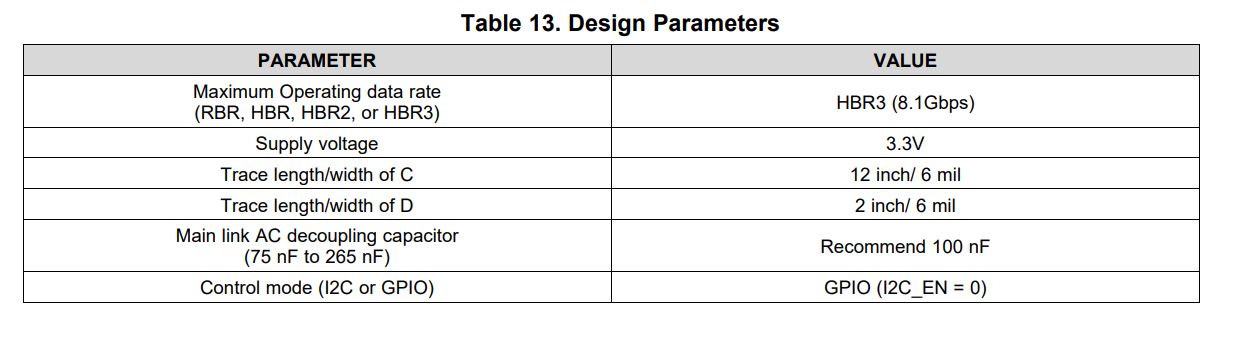
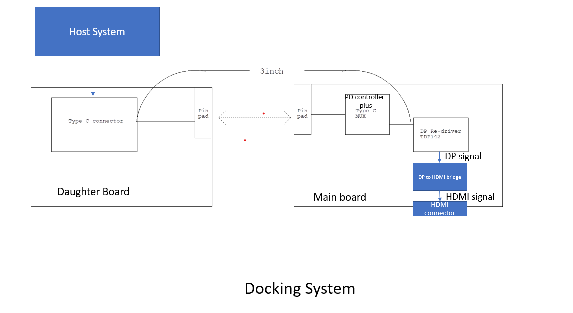
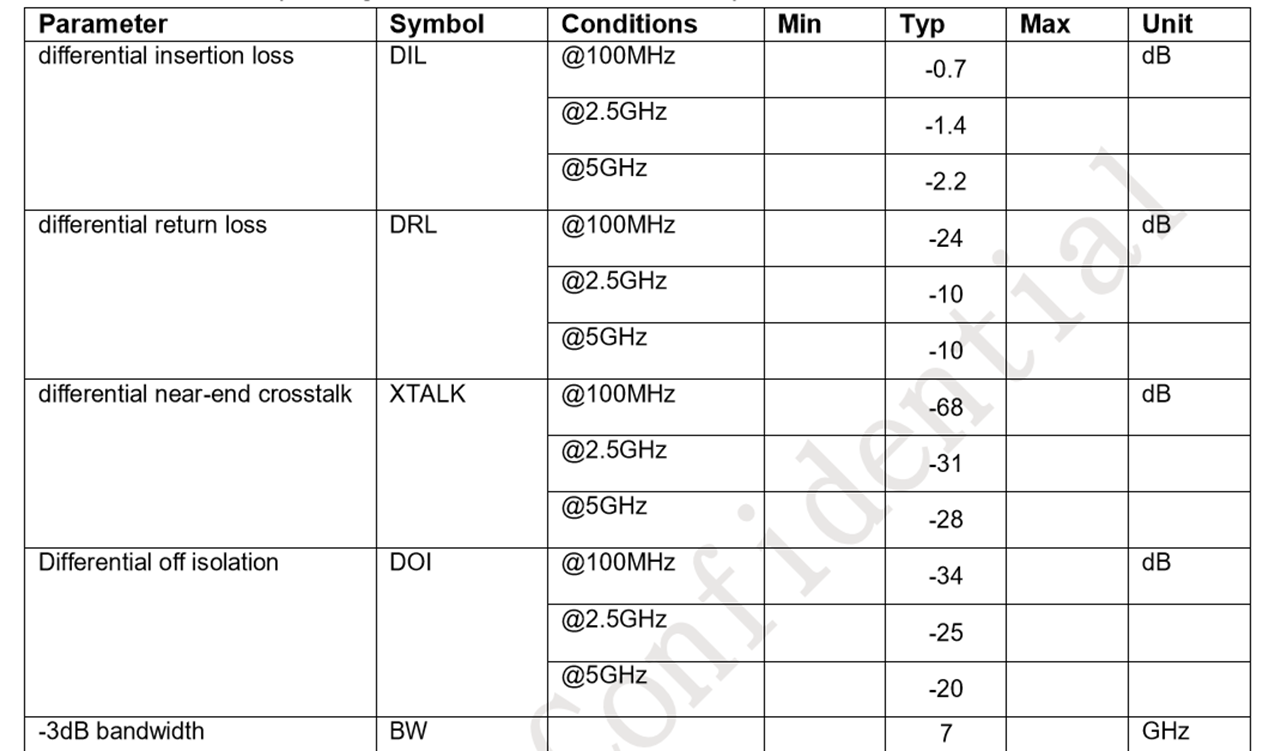
This is a type-c docking system with block diagram as below.  THe daughter board and main board would be connected through a 10-pin pad as shown in the bottom, but the signal loss of this pad is unknown.  What we know now is the trace length is totally around 3 inch from type-c connector to TDP142.  I think we also need to consider the loss of type-c mux (signal loss table as below) within the PD controller.  Do you see any concern for such application?  What is the signal loss acceptable from pin pad ?  WIll it be better to use SN65DP141?

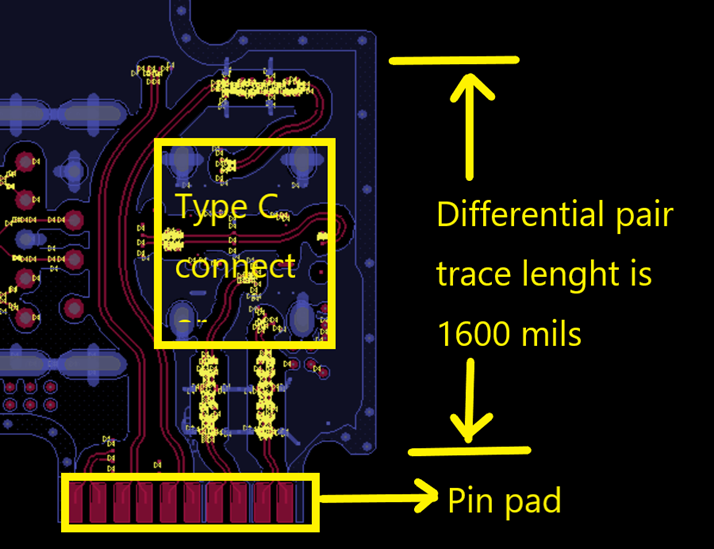
The layout of the pin pad would look like below.

TYPE-C MUX loss


Thanks,

Antony

  • Antony

    Why not use the TUSB1064 or TUSB564 for this application? The TUSB564 or the 1064 combines the function of the Type-C MUX and the DP142.

    Thanks

    David

  • Hi David,

    As described in the block diagram, they've chosen a PD controller embedded with type-c MUX function (non-TI solution) since the total cost is better.  Do you think we can support this scenario if they choose a stand alone PD controller plus TUSB1064?

    Thanks,

    Antony

  • Antony

    Sorry I missed the part which the PD controller already includes the Type-C MUX. In this case, you can use the DP142 in this design. Or like you said, a standalone PD controller plus the TUSB1064 will also work. 

    Thanks

    David

  • Hi David,

    Don't you think the trace loss could be too big from the type c connectir to TDO142?

    Thanks

    Antony

  • Antony

    The total trace length is 3in which is not a significant amount of loss. The key is the loss of the two pin pads and the Type-C MUX, and whether the total loss is within the TDP142 EQ compensation range.

    Thanks

    David

  • HI David,

    Thanks for your reply.  Based on the 3-inch trace length and the type-c mux listed below (need to support 8.1Gbps), what is the maximum of loss (dB) can be tolerated from the pin pad?

    In parallel, from TDP142 I thought that we can only accept max 2-inch of trace length from type-c connector to TDP142 even on a DP sink system.

    Thanks,

    Antony

  • Antony

    Please refer to Figure 17 and Table 13 in the TDP142 datasheet. Between the receptacle and the TDP142 which is PCB trace of length C, we recommended a 12in trace. The 3in insertion loss plus ~2.2dB MUX loss are within the TDP142 RX compensation range.

    Thanks

    David

  • Hi David,

    Thanks for clarification.  Does it mean the trace length from TDP142 to "DP to HDMI Bridge" should be less than 2-inch?  Or it depends on any parameter from the "DP to HDMI Bridge" datasheet?

    Is this "2-inch" defined in datasheet very strict?  Why can't we support a longer trance length here for our application scenario now?

    THanks,

    Antony

  • Antony

    Does it mean the trace length from TDP142 to "DP to HDMI Bridge" should be less than 2-inch? -> Correct

    The TDP142 is a linear redriver, it only has a RX equalizer, and does not have TX Swing or Pre-emphasis control. With a linear redriver, you want to place the TDP142 as far away from the source as possible (The distance between the Type-C connector and the TDP142) to maximize its RX equalizer capability as much as possible.

    The 2-in is not a hard requirement. But more a recommendation to give the Source TX and Sink (DP to HDMI) RX as much margin as possible. You can go longer than 2-in, but that's taking margin away from the Source TX and Sink RX.

    Thanks
    David